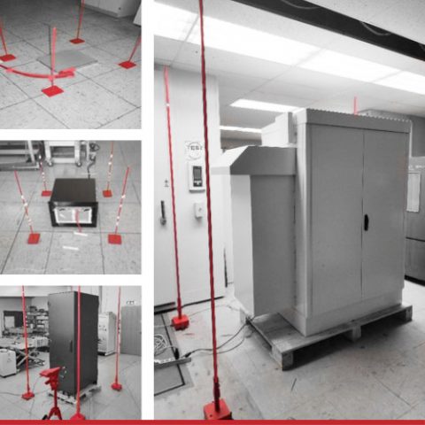
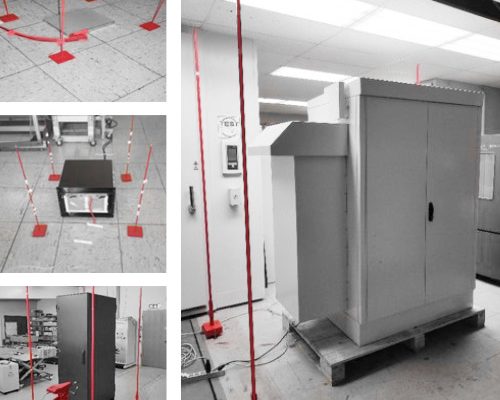
The packing density of electronic devices in measurement and test technology is continuously increasing – as is the resulting heat load and cooling requirement. This also affects the thermal management within the system. The increasing noise load can become problematic because of active cooling, especially in laboratory environments or offices. In order to keep noise levels as low as possible, a variety of factors must be carefully weighed: starting with the selection of the number and size of suitable fans, including the filter class and size, as well as the positioning of the air filter or filter blower, and the decision on which grilles should be used. Here for example, a distinction is made between air inlet grilles and air outlet grilles, as well as other features. For this reason, we at nVent recommend checking the final application for its acoustic limits and then proceeding with an in-house noise measurement.
1. Cause and effect: Sound power and sound pressure level
The sound power level is determined in order to allow an objective comparison of the sound power of different devices. In this case, sound power is the total airborne sound energy emitted by a sound source per unit of time. On the other hand, sound pressure is what our ears perceive as noise. The sound pressure is measured in decibels (dB) and is the result of the sound energy radiated by sound sources that is transmitted into an acoustic environment and measured at a specific location.
2. Combining components methodically: The acoustic design
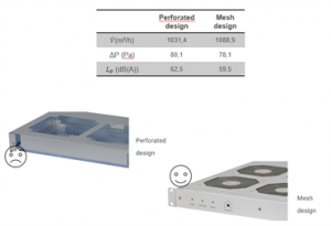
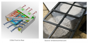
The acoustic design of any system should begin in the early stages of a product’s development. Two relevant parameters are of particular importance here: an optimized case design and the selection of a suitable fan. When designing the case, the aim is to avoid corners, edges, and narrow ducts, as these features generate noise. At this point, it is also checked whether perforated sheet metal or wire mesh for air intake and exhaust openings provide better results. The design of the appropriate fan is dictated by the installation site and the air resistance of the overall system: As an option, axial, radial, and diagonal models are available and included in the dimensioning of the fan’s design. Among other things, the operating point and the feasible fan stage in the final application are also taken into account during the design.
3. Focal point: Considering the system in its working environment
The blower noise depends on the performance of the fans and their speed – the higher the air volume and the resulting air pressure, the higher the noise generated by the fan. Conversely, this means that a low noise level can only be achieved if the influence of the system’s maximum power loss is taken into account, and the air volume and air pressure are reduced to the required minimum values. Furthermore, the air resistance of the cabinet, the system itself, or the case are also aspects that must be considered. Therefore, the air resistance must be kept as low as possible. We also recommend that a fan control system be provided in the application. This fan control system adjusts the cooling performance to the current demand and ensures a significant noise reduction at partial load.
4. Optimizing the temperature difference: maximum ambient and air outlet temperature
Delta T (ΔT) defines the permissible temperature range from the air inlet (ambient temperature) to the air outlet and significantly affects the system’s energy requirements. The following questions are factored in the calculation: How long is the maximum temperature expected to remain? Seconds, minutes, hours, days? Is the full electrical power required at the maximum temperature?
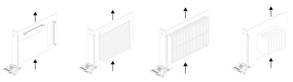
In order to reduce the cooling-related noise level, optimizing the airflow through the system is one of the most important considerations. This optimization starts with the plug-in cards, which should already be designed with ideal thermal performance in mind. Only the perfect placement of all components minimizes the occurrence of airflow blockages. At nVent, the appropriate size, architecture, and dimensions of the heat sink are already determined by model simulations during the development of the thermal concept. Furthermore, when the systems are assembled, the routing of the air to the hot spots can already be taken into account by closing empty slots through front panels with air baffles.
5. Alternative cooling concepts: Sound of Silence – Conduction-cooled cases
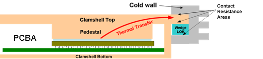
Depending on the application and location, different solution approaches are suitable for energy and noise-efficient cooling. Conduction cooling, for example, is used where the cooling process must not generate any noise and downtime due to defective fans must be prevented. These requirements can be met by either using a metal frame (Conduction Cooled Assembly – CCA)—installed on a printed circuit board—or by completely enclosing the printed circuit board with two halves of the case (clamshell). In turn, these are connected to the copper surfaces inserted into the PCB for cooling, as well as directly to the surface of the power-consuming components. Now, the heat is transferred from the hot spot to the CCA or clamshell and from there via a card retainer to the case and dissipated. It is important to know that thermal paste is required between the power-consuming components (processors or FPGAs) and the metal frame. This ensures good contact and compensates for any tolerances. However, when using such a cooling method—which was developed for a laboratory environment—it must be noted that the cooling performance is significantly lower than using forced air cooling. Such cooling requires plug-in cards specially developed for conduction cooling as well as other special components. This type of cooling is considerably more expensive to purchase than air-cooled systems.
6. Alternative cooling concepts: High efficiency – Liquid cooling solution for modular devices
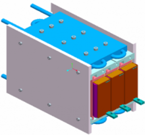
Even though using water as a cooling medium in technical environments is not readily accepted at the moment, two technologies for a very energy efficient cooling solution should be mentioned here: conduction-cooled cases with a water-cooled cooling pad, and liquid hot spot cooling. The methods used here include leaving fluid temperature (LFT) and spray cooling, which, however, is only possible with non-conductive media and thus has a limited range of applications. The associated hardware interfaces are quick disconnects (QD – quick disconnect) as well as non-drip and leak-proof valves. If using these two methods, it must be ensured that the infrastructure allows the use of these cooling solutions. Moreover, the initial costs are quite high, and the pumps and valves used contribute to noise pollution and must be mounted externally.
7. A question of prioritization: Which cooling solution “fits”?
In order to achieve the lowest possible noise level, optimizing all parts of the overall application is a must. The key is to find a suitable compromise between the achievable noise level, the cooling performance, and the budget available for this. Our tip: Evaluate the application. What performance is typically required at what temperature and in what type of environment?
Our experts provide a wide range of nVent SCHROFF hardware components, processes and services for the energy- and noise-efficient cooling of systems and equipment in test and measurement.
For a comprehensive overview of nVent SCHROFF product range, click here.