Understanding Sheath Theory and its relation to ground electrode system design is key to understanding the fundamental principles of design, ground resistance and soil resistivity measurements and computations. This following is part one of our four-part ground electrode design principles and testing series, which is based on our white paper “Ground Electrode Design Principles and Testing.” You can download the full white paper here.
- Sheath Theory
- Soil Resistivity & Measurement
- Calculating Ground Electrode Resistance Of A Single Rod
- Measurement Of Electrode Resistance
Sheath Theory – Distribution Of Voltage In Ground
To understand grounding principles, the first thing that we will consider, is how the voltage is distributed in the Earth when a current is injected into a vertical ground rod. The intuitive understanding of this will enable us to better appreciate why electrode designs are done a certain way. For example, this will help us to understand why we use deeper ground electrodes or radial electrodes.
The soil is non-uniform in its conductivity and this factor will need to be accounted for in the design of the ground electrode system. However to develop an understanding of the principles of the current flow and the voltage distribution in the ground, we will look a graphical model, which assumes uniform soil. This is called the sheath theory of expanding soil conductivity. In Figure 1, the hemispherical sheaths depict imaginary equipotential lines, which form in the ground when a current is injected into a vertical ground rod.
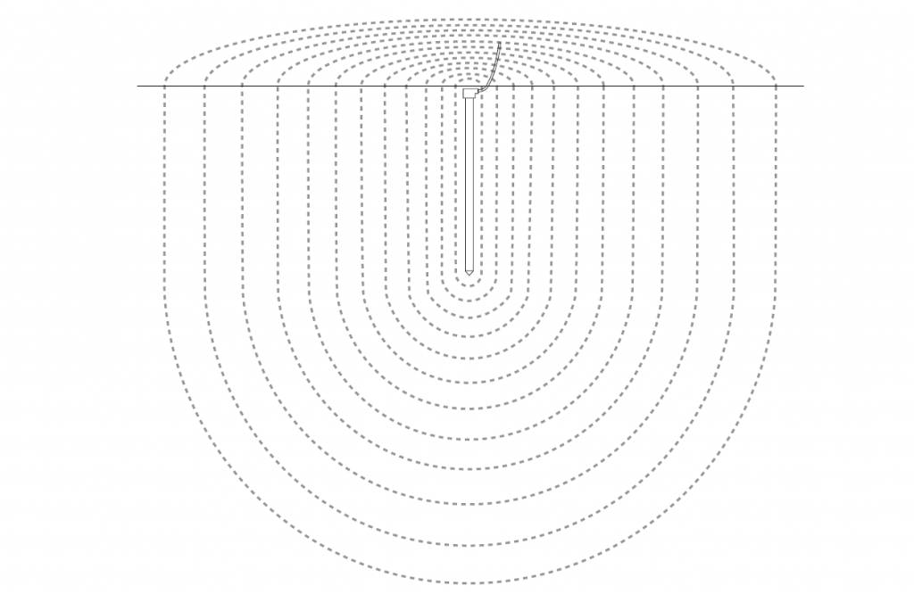
Figure 1: Equipotential lines caused in ground when a current is injected in a vertical ground rod. (Sheath Theory)
The Electrode Resistance
The electrode resistance is that resistance offered to the flow of current into the ground down to the expanse where the resistance of the ground becomes so low that it becomes negligible.
Consider the cut away section of the sheaths surrounding the ground electrode in Figure 1. In simple terms this resistance can be explained by the following relationship.
R α 1/A
where R is the resistance and A the area of each of the sheaths.
As the distance from the ground rod increases, the surface area of the sheaths, get larger. This means that at some distance, the additional soil area has negligible effect on the ground resistance.
It is for this reason, when measuring ground resistance to a remote earth, the test only needs to be confined to few tens, perhaps a few hundred of meters. For example, when testing a single 2-meter electrode, the test is only referenced to remote earth at distance of about 60-100 meters. Any greater reference distance than this would add insignificantly to the resistance. Testing of earth resistance is discussed in more detail later in this series.
It is easier to see which dimensions of the earth electrode will have a greater impact on the electrode resistance, if we consider what happens to the area of the hemispherical sheaths. In Figure 2, we see that when the electrode is made longer, the area increases significantly. Hence 1/A reduces giving us a reduction in the ground resistance. However, if the diameter of the ground rod is increased, this offers very little change in the area of the hemispherical shells and hence little changes in the resistance.
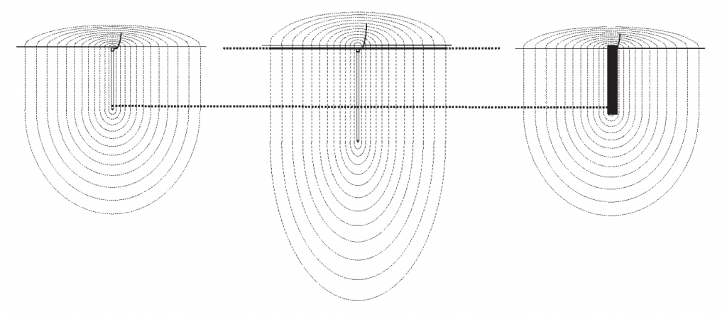
Figure 2: Effect of Longer and Deeper Ground Rods on Ground Resistance
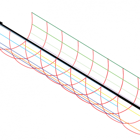
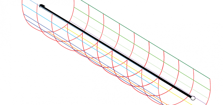
This intuitive understanding can be extended to horizontal electrodes. It can be seen in Figure 3 that making a horizontal electrode longer will increase the surface area of the sheaths surrounding it. Hence longer electrodes rather than deeper electrodes, will give a greater reduction in the electrode resistance.
Another factor that will have an impact on the ground resistance is the conductivity or the resistivity of the soil. In fact it is this factor that makes it impossible to have a “one size fit all” grounding design for different sites.
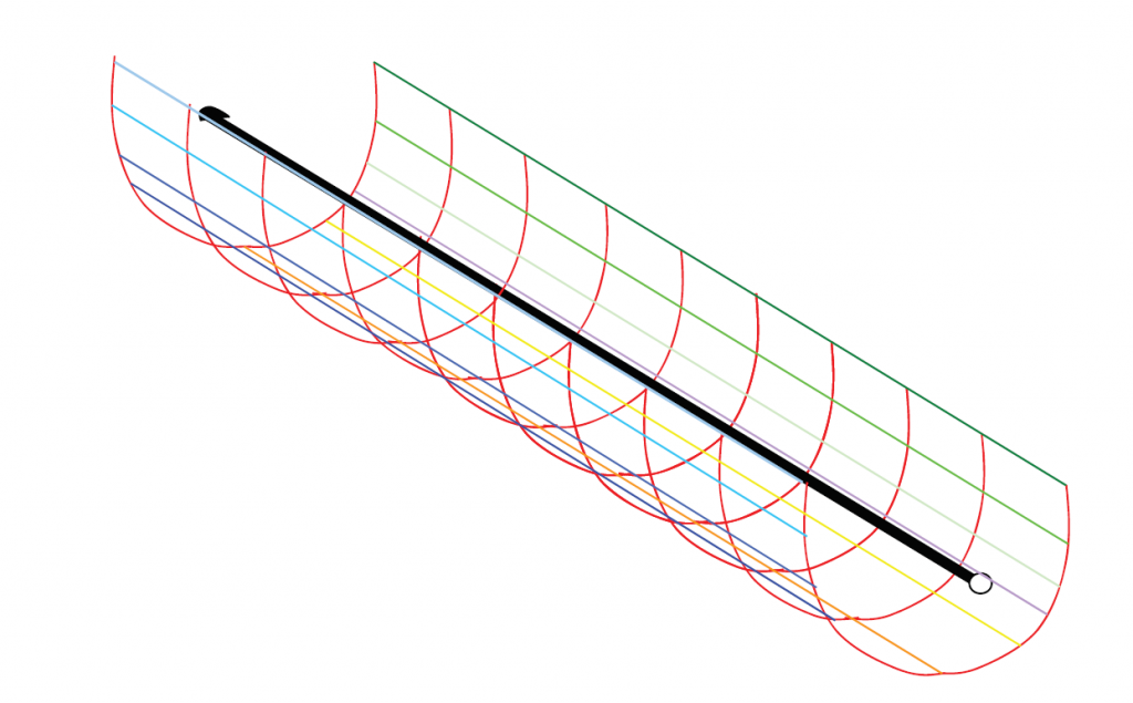
Figure 3: Sheath Theory on Horizontal Electrodes
Download the nVent ERICO Ground Electrode Design Principles and Testing White Paper
Download the white paper below that captures the fundamental principles of ground electrode design, ground resistance and soil resistivity measurements and computations. form a basis for understanding the reasoning behind incumbent grounding practices and will act as a guideline to an engineer trying to grasp the essence of ground electrode design.
Electrical Engineers: Your Source for Electrical News and Advice
Stay on top of new trends, advice and information by subscribing to the nVent ERICO blog. Our electrical engineering and product experts regularly publish new information, and also curate top resources with posts like this one.