Understanding the measurement of electrode resistance in relation to ground electrode system design is key to understanding the fundamental principles of design, ground resistance and soil resistivity measurements and computations. This following is part one of our four-part ground electrode design principles and testing series, which is based on our white paper “Ground Electrode Design Principles and Testing.” You can download the full white paper here.
- Sheath Theory
- Soil Resistivity & Measurement
- Calculating On Ground Electrode Resistance Of A Single Rod
- Measurement Of Electrode Resistance
Measurement Of Electrode Resistance
When an electrode system has been designed and installed, it is usually necessary to measure and confirm the ground resistance between the electrode and “true Earth.” The most commonly used method of measuring the ground resistance of a ground electrode is the 3-point measuring technique shown in Figure 10. This method is derived from the 4-point method, which is used for soil resistivity measurements.
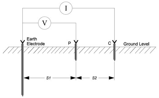
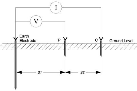
Figure 1: The 3-point method of ground resistance measurement
The 3-point method, called the “fall of potential” method, comprises the ground electrode to be measured and two other electrically independent test electrodes, usually labelled P (Potential) and C (Current). These test electrodes can be of lesser “quality” (higher ground resistance) but must be electrically independent of the electrode to be measured. An alternating current (I) is passed through the outer electrode C and the voltage is measured, by means of an inner electrode P, at some intermediary point between them. The ground resistance is simply calculated using Ohm’s Law; Rg = V/I, internally by the test equipment.
When performing a measurement, the aim is to position the auxiliary test electrode C far enough away from the ground electrode under test so that the auxiliary test electrode P will lay outside the effective resistance areas of both the ground system and the other test electrode (see Figure 2).
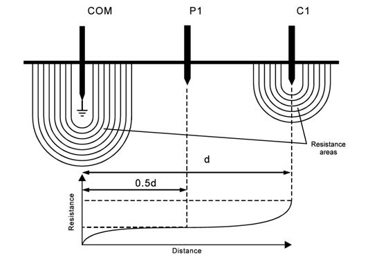
Figure 2: Resistance areas and the variation of the measured resistance
If the current test electrode, C, is too close, the resistance areas will overlap and there will be a steep variation in the measured resistance as the voltage test electrode is moved. If the current test electrode is correctly positioned, there will be a ‘flat’ (or very nearly so) resistance area somewhere in between it and the ground system, and variations in the position of the voltage test electrode should only produce very minor changes in the resistance figure.
The instrument is connected to the ground system under test via a short length of test cable, and a measurement is taken.
Measurement accuracy can be affected by the proximity of other buried metal objects to the auxiliary test electrodes. Objects such as fences and building structures, buried metal pipes or even other grounding systems can interfere with the measurement and introduce errors. Often it is difficult to judge, merely from visual inspection of the site, a suitable location for the tests stakes and so it is always advisable to perform more than one measurement to ensure the accuracy of the test.
Fall of Potential Method
This is one of the most common methods employed for the measurement of ground resistance and is best suited to small systems that don’t cover a wide area. It is simple to carry out and requires a minimal amount of calculation to obtain a result.
The outer test electrode, or current test stake, is driven into the ground a good distance away from the ground system. This distance will depend on the size of the system being tested and the inner electrode, or voltage test stake, is then driven into the ground mid-way between the ground electrode and the current test stake, and in a direct line between them.
| Maximum dimension across ground system, d | Distance from ‘electrical center’ of ground system to voltage test stake | Minimum distance from ‘electrical center’ of ground system to current test stake, 0.5d |
| 1 | 15 | 30 |
| 2 | 20 | 40 |
| 5 | 30 | 60 |
| 10 | 43 | 85 |
| 20 | 60 | 120 |
| 50 | 100 | 200 |
| 100 | 140 | 280 |
Figure 3: Variation of current and voltage electrode separation with ground grid size
The outer test electrode, or current test stake, is driven into the ground a good distance away from the ground system. This distance will depend on the size of the system being tested and the inner electrode, or voltage test stake, is then driven into the ground mid-way between the ground electrode and the current test stake, and in a direct line between them.
The Fall of Potential method incorporates a check to ensure that the test electrodes are indeed positioned far enough away for a correct reading to be obtained. It is advisable that this check be carried, as it is really the only way of ensuring a correct result.
To perform a check on the resistance figure, two additional measurements should be made; the first with the voltage test electrode (P) moved 10 percent of the original voltage-electrode-to-ground system separation away from its initial position, and the second with it moved a distance of 10 percent closer than its original position, as shown in Figure 4.
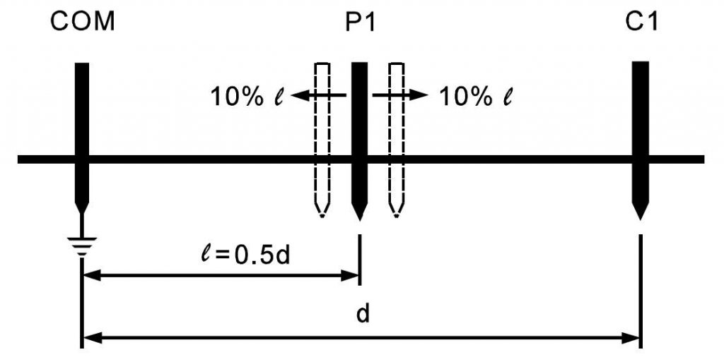
Figure 4: Checking the validity of a resistance measurement
If these two additional measurements are in agreement with the original measurement, within the required level of accuracy, then the test stakes have been correctly positioned and the DC resistance figure can be obtained by averaging the three results. However, if there is substantial disagreement among any of these results, then it is likely that the stakes have been incorrectly positioned, either by being too close to the ground system being tested, too close to one another or too close to other structures that are interfering with the results. The stakes should be re-positioned at a larger separation distance or in a different direction and the three measurements repeated. This process should be repeated until a satisfactory result is achieved.
The Slope Method
This method is suitable for use with large grounding systems, such as substation ground. It involves taking a number of resistance measurements at various ground electrode to voltage electrode separations and then plotting a curve of the resistance variation between the ground and the current. From this graph, and from data obtained from the tables, it is possible to calculate the theoretical optimum location for the voltage electrode and thus, from the resistance curve, calculate the true resistance.
It is similar to the fall of potential method but several readings are taken by moving the inner test electrode from very close to the ground grid to the position of the outer test electrode. The readings obtained are then plotted on a graph. Figure 5 shows an example of the graph obtained. It can be observed that at approximately 60 percent of the distance the slope is the gentlest and the resistance corresponding to this is the true resistance of the electrode being measured. In this case it is 20 ohms.
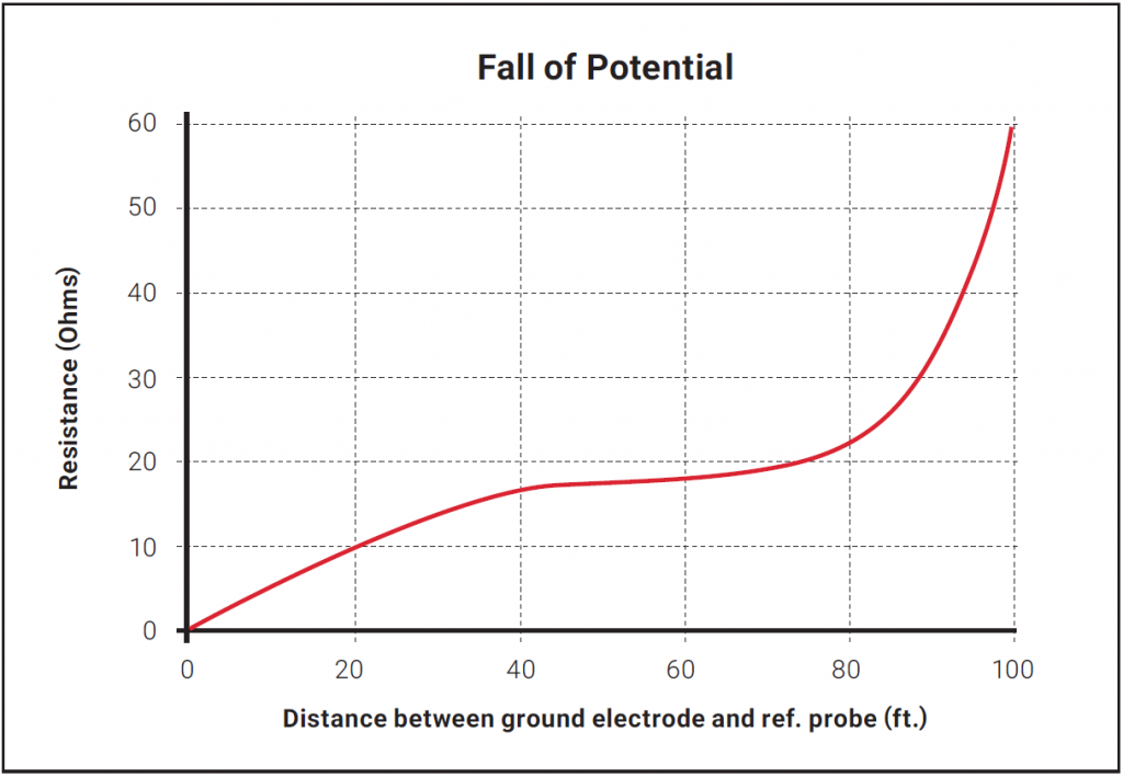
Figure 5: Typical graph, slope
For full details of this method, refer to paper 62975, written by Dr G.F. Tagg, taken from the proceedings of IEEE volume 117, No 11, Nov. 1970.
Download the nVent ERICO Ground Electrode Design Principles and Testing White Paper
Download the white paper below that captures the fundamental principles of ground electrode design, ground resistance and soil resistivity measurements and computations. form a basis for understanding the reasoning behind incumbent grounding practices and will act as a guideline to an engineer trying to grasp the essence of ground electrode design.
Electrical Engineers: Your Source for Electrical News and Advice
Stay on top of new trends, advice and information by subscribing to the nVent ERICO blog. Our electrical engineering and product experts regularly publish new information, and also curate top resources with posts like this one.