
Electrical connections are frequently the weakest component in the flow of currents within power conductors. These connections serve a wide range of applications, and loose connections are the primary cause of electrical failures, contributing to an estimated 30% or more of all such incidents.
Consequently, they are a major contributor to power outages and the loss of critical services.[1] Additionally, heating due to poor connections can result in catastrophic failures such as arc flash or fires in panel boards and buildings.
While some mission-critical installations may employ dual redundant power systems, most applications do not have redundancy in their connections, despite having redundancy in other equipment like uninterruptible power supplies (UPS) and standby generators. Similarly, while various electrical equipment are monitored for potential failures, it is uncommon to have monitoring systems in place for detecting heating and other defects in connections. The closest approach to monitoring connection integrity in installations is through regular maintenance, including infrared fault detection.
The purpose of this article is to emphasis the importance of creating durable and correct power connections to ensure that the job is executed properly from the outset, thereby preventing future failures.
IMPORTANT COMPONENTS IN COMPRESSION CONNECTIONS
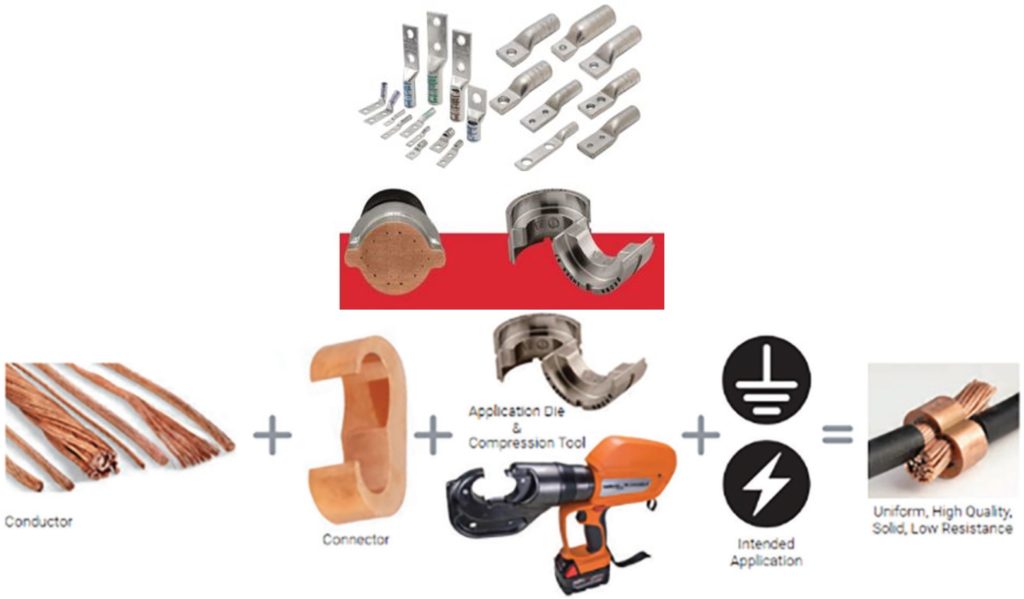
Compression and mechanical connections are the predominant types of connections used in power systems. Ensuring a reliable power system necessitates the proper selection and application of tools for compression connections. It is crucial to pay attention to the following aspects of compression connections:
- The Conductor
- The Connector
- The Compression tool
- The Compression die
- The Correct force
- Inspection regime
THE CONDUCTOR AND THE COMPRESSION CONNECTORS
It is uncommon for a manufacturer to produce both conductors and lugs. As a result, matching lugs or connectors with cables can be challenging, particularly when using specialised cables.
Generally, cables are manufactured according to IEC 60228 Standard, classified as Class 1, 2, 5, or 6. While the number of strands and cross-sectional area is well-defined, variations in the outer diameter of cables may occur due to differences in manufacturing techniques and stranding types. These stranding configurations may include concentric, bunched, roped, sectors, segmented, annular, or compacted forms. Consequently, conductors with the same cross-sectional area can exhibit a range of outer diameters.
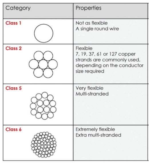
Classes of Cables – Keystone Cables [6]
The significant variations in stranding and compacting can complicate the selection process for lugs
or connectors. Cable connections or lugs are critical components in any electrical system, functioning as the interfaces between wires and terminals. These essential parts ensure that electrical connections are secure and reliable.[5]
Connection and tooling manufacturers can provide guidance on the selections of correct connections to suit your cable type. On some occasions the manufacturer can also perform tests like pull out test or continuous current tests on cable to connector applications that have not previously been tested. Good manufacturers will have the lugs for a particular cross section tested to multiple or all types of stranding for that conductor.
Before compression, a typical cross section of cable consists of 75% metal and 25% air. After compression, there is significantly less air left in the connections. Copper connectors and lugs are used only on copper conductors. Aluminum connectors and lugs may be used on both copper and aluminum conductors. Aluminum Type AL9 is used only on aluminum conductors, while aluminum type AL9CU can be used with both copper and aluminum conductors.
The cable connection or lug will have certain markings that may include:
- Manufacturer
- Wire Size
- Wire Material (CU, AL, or AL9CU indicating dual rating)
- Crimp Indicator Bands
- Compliance or Listing Information
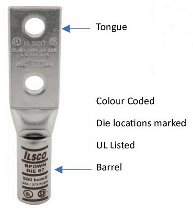
Connectors are often banded with coloured stripes to indicate the number and location of each crimp. They may also be marked with the die code number at the compression location. It is important to follow the manufacturer’s instructions regarding whether to crimp on the coloured bands or between them. When crimped, the die code number or other marking will be embossed on the connector for easy inspection to determine if the correct die and connector combination was used. As dies can be from multiple manufacturers, some manufacturers provide cross references with commonly available brands.
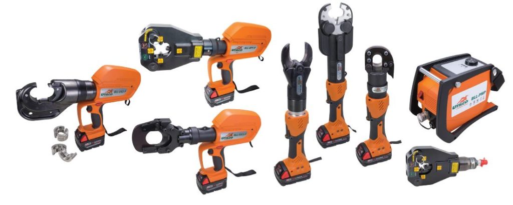 Example of Powered Hydraulic Tools | 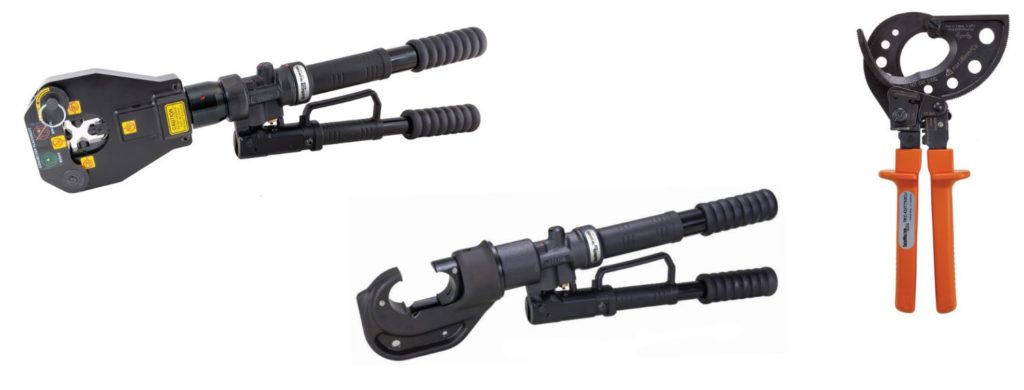 Example of Manual Hydraulic & Cutting Tools |
THE COMPRESSION TOOLS AND DIES
The correct tool and dies should be used for the connector and the conductor combinations.
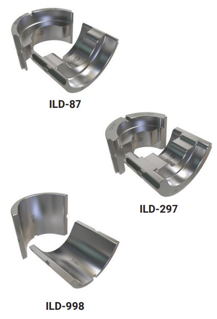
U-Dies
U-Dies are a prevalent type of die and are typically compatible with various brands of tools available in the market. They fit into the jaw of the nVent ILSCO 12-ton crimping tool and most of other common crimping tools within the 12-ton range. Constructed from hardened stainless steel, these dies ensure durability and long life, and they are available separately for copper and aluminum lugs. Additionally, U-Dies are available for grounding crimps such as nVent ERICO PermaGround C, E, and Figure 6 Crimps.
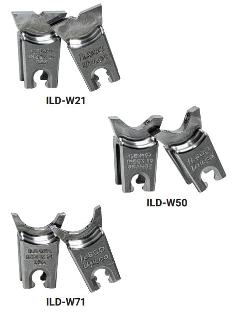
W-Dies
W-Dies are commonly used for cable lug crimping and are designed for use with custom 6-ton crimping tools. These dies have been compliance tested with nVent ILSCO and other brand’s lugs, fitting into the nest of the nVent ILSCO in-line 6-ton crimping tool. Like U-Dies, W-Dies are made from hardened stainless steel for longevity and are available either separately or in kits for copper and aluminum.
Cable lug connections can also be made using die-less tools suitable for a wide range of conductor sizes from 10 mm² to 500 mm². These versatile tools are compatible with lugs and connectors from multiple manufacturers. Compression tools for creating electrical connections are offered in capacities ranging from 6 to 13 tons.
MECHANICAL CONNECTORS
Unlike compression connectors, mechanical connectors are typically designed to accommodate a range of conductors. It is crucial to verify that the cable falls within the specified range listed on the connector. When the connector is intended for use on a bus, pad, or equipment, it is essential to tighten the mounting hardware according to the manufacturer’s specifications. Proper termination of the conductor, application of conductive compounds where recommended, and adherence to the correct torque specifications are important factors to ensure optimal performance.
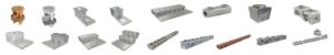
Examples of Mechanical Connectors
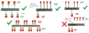
Load Balancing in Multi Port Connectors
Load balancing is another critical aspect when utilising multi-port mechanical connectors. Below are examples of acceptable and unacceptable connections for multi-port configurations.
The use of mechanical connectors with multi-stranded or flexible cables requires careful consideration. Most mechanical connectors feature conical wire binding screws. However, some screws are not suitable for use with flexible cables and may cause damage to the wires. Torque compensating screws are a superior option for connecting flexible cables. These screws have a disk pad at their base that is separated by a Belleville washer, providing torque control and preventing damage to the flex conductors.
Other types of mechanical connectors include insulated connectors, waterproof connectors, safe breakaway connectors, and insulated piercing connectors. These topics are beyond the scope of this article, but we plan to provide future editorials in this publication to discuss these connection types in detail.
References
- Top 10 Electrical Failures By Cause –Graceport Technologies
- Prediction of failure in time (FIT) of electrical connectors with short term tests. Jian Song*, Abhay Shukla, Roman Probst, Precision Engineering Laboratory, Ostwestfalen–Lippe University of Applied Sciences, Lemgo, German
- Failure due to poor termination & loose connections in electrical systems, April 2018 Water and Energy International 61(1):48-51 P.K. Gore P. Gore
- How to Avoid Loose Electrical Connections and Prevent Fire Hazards Angela Jones February 28, 2024
- Choosing the right cable lugs for your electrical projects, I. U, Elec.
- What are the different classes of cables, Keystone Cables.
- Connector Installation Guide Compression and Mechanical Connectors, nVent ILSCO
- Training materials – Mechanical Connectors by Andy Zwit, nVent ILSCO
If you want to learn more about nVent ERICO, please visit our website, www.nvent.com/erico.
CONTACT US