Understanding soil resistivity & measurement and its relation to ground electrode system design is key to understanding the fundamental principles of design, ground resistance and soil resistivity measurements and computations. This following is part two of our four-part ground electrode design principles and testing series, which is based on our white paper “Ground Electrode Design Principles and Testing.” You can download the full white paper here.
- Sheath Theory
- Soil Resistivity & Measurement
- Calculating Ground Electrode Resistance Of A Single Rod
- Measurement Of Electrode Resistance
Soil Resistivity
Soil resistivity is another name for the specific resistance of the soil. It is measured in ohm-meters or ohm-centimeters. An ohm-meter is that resistivity of the soil when it has a resistance of 1 ohm between opposite faces of a cube with one meter sides.
Resistance is directly proportional to soil resistivity. This relationship is not as easy to compute in real life as it may sound, because soil resistivity will inevitably vary with depth. The second difficulty in dealing with different locations is that the resistivity varies greatly with sites.
The tables below give an idea of the resistivity of several mediums that are of interest for the design of grounding system.
| Material | Typical Resistivity |
| Copper | 1.72 x 10⁻⁸ ohm.m |
| GEM, Material | 0.12 ohm.m |
| Bentonite | 2.5 ohm.m |
| Concrete | 30 to 90 ohm.m |
Factors that will affect the resistivity of the soil are the soil type, compactness, chemical composition, temperature and water content. Figure 1 shows the effect of moisture content and temperature on soil resistivity.
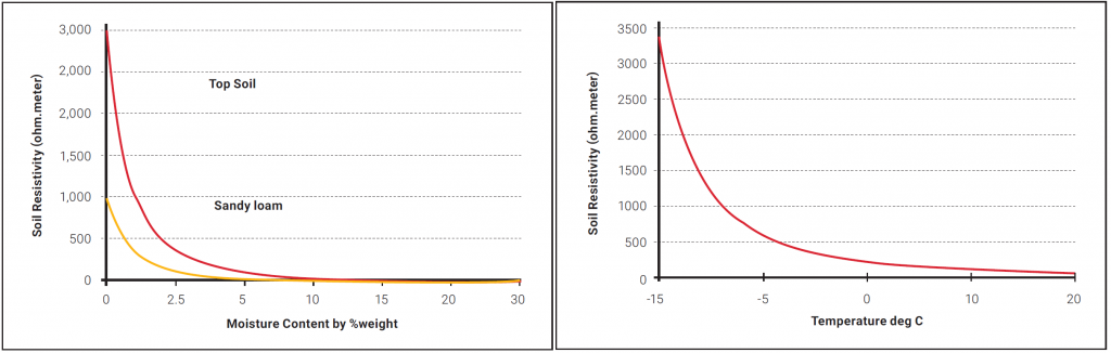
Figure 1: Effect of moisture content and temperature on the soil resistivity
Measurement of Soil Resistivity
There are several methods of measuring the soil resistivity.
These include:
- Wenner Array 4-Point Method
- Schlumberger Array
- Driven Rod Method
The Wenner Array method is discussed in this paper because this is the most common method of measuring soil resistivity. The scope of this document does not allow detailed discussion on other soil testing methods.
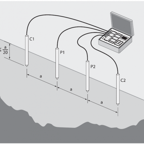
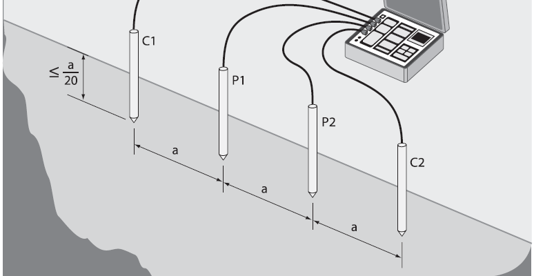
Using the Wenner Array method, four small electrodes (auxiliary probes) are placed in a straight line at intervals of a, to a depth of b. A current is passed through the outer two probes, and the potential voltage is then measured between the two inner probes. A simple Ohm’s Law equation determines the resistance. From this information, it is now possible to calculate the resistivity of the local soil. For most practical circumstances, “a” is 20 times larger than “b”, where we can then make the assumption that b=0.
Then the Resistivity, ρ, is given by:
ρ = 2 π a Re
where
ρ = Resistivity of the local soil (Ω-m)
a = distance between probes (m)
b = depth of probes into the ground (m)
Re = resistance value measured by the testing device (Ω)
These values give an average resistivity of the soil to a depth a. It is recommended that a series of readings be taken at different values of a, as well as in a 90° turned axis. It is a good practice to tabulate or plot the results because that gives a good idea of how the resistivity is changing with depth and will give us a better clue on the type of ground electrode to design.
For example, if the resistivity is very high at the top three meters but drastically drops after that depth, then one would consider designing using electrodes that are driven or drilled to deeper than three meters. Conversely if the resistance does not improve beyond a certain depth, say two meters, then horizontal electrodes may be considered in the ground electrode design.
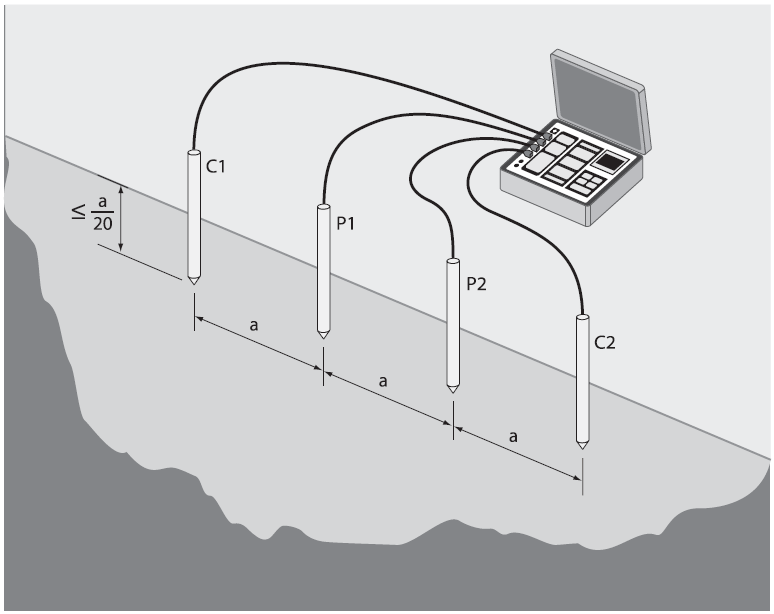
Figure 2: Wenner Array (4 Point Method)
Figure 2 shows a typical record sheet for resistivity measurements. Experience has shown that many testers of the soil resistivity often do not have a full appreciation of the extent to which the test needs to be carried out. It is often noted that only a single or a handful of values are measured. It is recommended that for the design of ground electrode, a comprehensive set of results be gathered in the range of 2–40 meters.
| Spacing, a | Measured Value of Re | Resistivity, R = 2 π a Re |
| 2 | ||
| 4 | ||
| 6 | ||
| 8 | ||
| 10 |
Download the nVent ERICO Ground Electrode Design Principles and Testing White Paper
Download the white paper below that captures the fundamental principles of ground electrode design, ground resistance and soil resistivity measurements and computations. form a basis for understanding the reasoning behind incumbent grounding practices and will act as a guideline to an engineer trying to grasp the essence of ground electrode design.
Electrical Engineers: Your Source for Electrical News and Advice
Stay on top of new trends, advice and information by subscribing to the nVent ERICO blog. Our electrical engineering and product experts regularly publish new information, and also curate top resources with posts like this one.