Proper grounding proves to be an important issue when designing and installing power and lightning protection systems. The goal of any grounding system is to provide a low-impedance path for fault and lightning-induced currents to enter the earth, ensuring maximum safety from electrical system faults and lightning.
A properly installed grounding system not only helps protect buildings and equipment from damage caused by unintentional fault currents or lightning surges, but more importantly, it also protects people.
Grounding is a very complex subject. The proper installation of grounding systems requires knowledge of national and international standards, grounding conductor materials and compositions, and grounding connections and terminations. However, designers and installers of grounding systems should not overlook another important factor—soil conditions.
Below, we explore what soil resistivity is, how it is determined and the ways in which grounding systems are affected by various soil resistivity.
What Is Soil Resistivity?
Quite simply, soil resistivity is how resistive the soil is to the flow of electricity. In the majority of applications, a low ground resistance is preferred or even require, therefore more often than not a low resistivity is preferred. In a number of applications, the ground resistance itself is not as critical as the grounding layout (i.e. grid, mesh, etc.). However, despite this, a high soil resistivity still represents challenges to these designs and can exasperate shortcomings or under design.
Preferably, a measurement of the soil resistivity is conducted before the grounding system is designed. A common method to achieve this is the Wenner 4-Point Test, which involves four probes spaced at equal distances to determine the profile of the soil resistivity at various depths. Understanding how the soil resistivity varies with depth is important for the designer, as it can determine if a deep or shallow ground electrode design is desired.
In addition to the type of soil, other factors that can influence soil resistivity are temperature and moisture level. Because of this, change in season or weather patterns can have an impact on soil resistivity, and therefore grounding system performance. For example, soil with low resistivity during humid, warmer seasons may have a higher resistivity during cold (freezing as an extreme) or dry seasons.
Since testing soil resistivity is not always possible, be aware of the factors affecting soil resistivity:
- Soil type. Rocky soil or gravel has especially high resistivity.
- Moisture content level. Dry ground, like sand in a desert, is highly resistive.
- Temperature. Cold or frozen ground will be more resistive than warm ground.
- Mineral content. Igneous rocks, for example, are more resistive than ore minerals.
- Contaminants. Could be metals, salts or other substances, like oil.
The chart below shows some of the ranges in resistance for typical soil types:
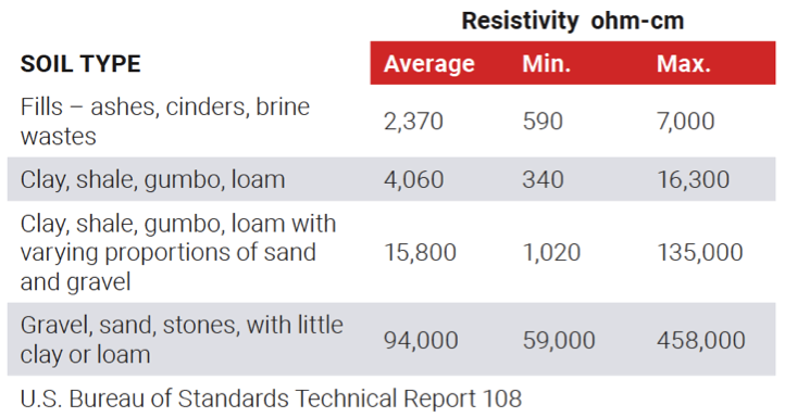 *Typical resistivity for various soil types
Why Soil Resistivity Matters for Grounding
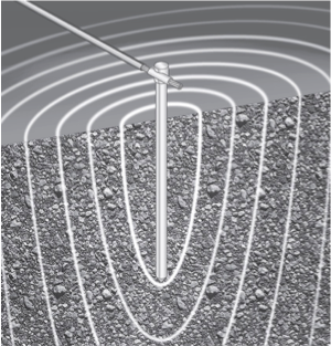 When currents flow from a ground electrode into the surrounding soil, they’re often described as flowing through a series of concentric shells of increasing diameter. Each successive shell has a greater area for current flow and consequently, lower resistance. At some point distant from the earth conductor, the current dissipation becomes large enough and the current density small enough that the resistance is negligible.
If the soil has high resistivity, and the ground electrode not sufficiently arranged to offset this, the dissipation of the electrical current running through the system will result in a higher voltage on the grounding system. This has implications in certain application such as higher touch or step potentials, or in more extreme cases failure of reliable operation of over-current or over voltage devices.
The Most Cost-Effective Grounding Solution for High Resistivity Soil
To finalize the dissipation of a lightning current safely into the earth, high conductivity ground must be present. Conductive enhancement materials are some of the most cost-effective ways to overcome high soil resistivity. These materials are ideal for use in areas with high resistivity soils, including rocky earth, mountaintops and sandy soil. These products can be referred to as “grounding” or “earthing” enhancement materials.
 Low ground resistance can also be achieved with other techniques, such as:
- Deeper driven electrodes
- Multiple rods bonded together
- Counterpoise system
- Coupled rods
- Chemical rods
Depending on the application, conductive ground enhancement material is often preferred over the aforementioned options. Due to the conductive benefits of the material, fewer grounding electrodes may be required to achieve the targeted ground resistance saving both time and money on the total installation.
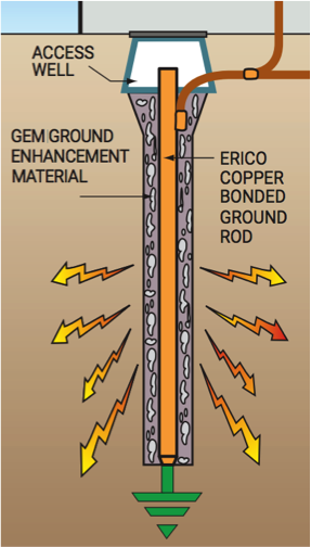
How Does Enhancement Material Work?
Enhancement material is installed around a ground electrode in a vertical or horizontal orientation as a highly conductive path to dissipate the current to ground.
These materials are available in a variety of compounds. Bentonite clay, for example, is a naturally occurring compound sometimes used, while commercially available forms include powders, pellets and gels. However, enhancement materials are most often cement-based, which require mixing and setting.
When considering alternatives, assess according to:
- Conductivity
- Installation ease and time
- Durability and reliability (i.e. does not dissolve, decompose or leach out)
- Corrosion resistance with the grounding electrode
Delve Deeper On Grounding Solutions
Discover best practices on grounding and bonding from the leaders in facility electrical protection. The ERICO Grounding and Bonding Solutions Guide provides in-depth information on the key standards, practices and techniques that will help protect various facility types from electrical events.