

 A surge protective device (SPD) is designed to protect electrical systems and equipment from surge events by limiting transient voltages and diverting surge currents.
Surges can originate externally, most intensely by lightning, or internally by the switching of electrical loads. The sources of these internal surges, which account for 65% of all transients, can include loads turning on and off, relays and/or breakers operating, heating systems, motors and office equipment.
Without the appropriate SPD, transient events can harm electronic equipment and cause costly downtime. The importance of these devices in electrical protection is undeniable, but how do these devices actually work? And what components and factors are central to their performance?
How Does a SPD Work?
In the most basic sense, when a transient voltage occurs on the protected circuit, an SPD limits the transient voltage and diverts the current back to its source or ground.
To work, there must be at least one non-linear component of the SPD, which under different conditions transitions between a high and low impedance state.
At normal operating voltages, the SPDs are in a high-impedance state and do not affect the system. When a transient voltage occurs on the circuit, the SPD moves into a state of conduction (or low impedance) and diverts the surge current back to its source or ground. This limits or clamps the voltage to a safer level. After the transient is diverted, the SPD automatically resets back to its high-impedance state.
SPD Categories or Types
The two main types of SPDs are voltage limiting and voltage switching components. Voltage limiting components change in impedance as the voltages rise, resulting in clamping the transient voltage. Voltage switching components “turn on” once a threshold voltage is exceeded and immediately drop to a low impedance. Most systems today incorporate both component types together to aggregate the strengths and limit the weaknesses of each individual part.
Examples of voltage limiting components are metal oxide varistors (MOVs) and transient voltage suppression (TVS) diodes. Voltage switching components include gas discharge tubes (GDTs) and spark gaps.
How to Compare SPD Categories
Surge components can be compared in how they perform according to the following factors.
Response Time
The response time of a given component simply means how quickly the component reacts when the surge threshold is surpassed. Voltage limiting components—TVS diodes, in particular—have faster response times than voltage switching components (i.e. spark gaps and GDTs).
Follow-On Current
This occurrence is limited to voltage switching devices. Follow-on current occurs when a surge protective device fails to “turn off’ (i.e. return to a high impedance state) following the transient event due to the low voltage drop across the component. This allows current to continue to flow through the device during normal operation.
This phenomenon is less of a concern in AC systems, as the zero crossing allows the component to turn-off and return to a high impedance state. However, a DC system using voltage-switching devices requires further consideration.
Let-Through Voltage
In the event of a surge, the let-through voltage is the amount of voltage the component allows to reach the connected equipment. For let-through voltage, diodes limit voltage the best and keep it the lowest, but that advantage is restricted because diodes are not as effective at handling larger surge currents.
One component not mentioned above as being one of the best or worst in any of these three areas is a MOV, because MOVs are generally considered serviceable in every category, operating as a jack-of-all-trades, but not the best in a single one.
Note that most SPD products on the market today are hybrid designs that are a combination of multiple surge components. These products balance the pros and cons of each individual component to provide facilities with balanced protection against various types of surges.
Surge Protective Device Performance Features to Know
Knowing individual surge components is helpful to understand, but what drives the standards for SPDs are performance aspects or features for each device.
After identifying the power distribution system to which the SPD is to be connected, one should compare different available devices by the following:
1. Maximum Continuous Operating Voltage (MCOV). The MCOV is the maximum voltage the device can withstand and continue to properly operate. Generally, the MCOV should be at least 25% above the nominal supply voltage, but is driven by the relevant standards. For example, nVent ERICO SPDs designed for 120 nominal volt devices have an MCOV of 170, and for 240 nominal volt systems the SPD’s MCOV is 275.
2. Voltage Protection Rating (VPR) or Voltage Protection Level (Up). Voltage protection rating and voltage protection level are ratings defined by UL and IEC, respectively, that relate to the let-through voltage of the device. UL 1449 includes a test that applies a 6kV/3kA combination waveform to the device and measures the voltage let through, determining the voltage protection rating (VPR). IEC 61643-11 has a similar test and refers to it as voltage protection level (Up).
3. Nominal Discharge Current (In) Rating. Defined as the peak value of a current that can be conducted through the SPD with a waveshape of 8/20μs where the SPD still functions after 15 applied surges. Per UL 1449, manufacturers must choose a nominal discharge current from a predefined list (3ka, 5kA, 10kA or 20kA) for this test.
4. Indication Status. The status indicator—which may be a mechanical indicator, LED or remote alarm—provides a simple Go/No-Go indicator.
Surge rating is something many consider a key factor for SPD specification. However:
5. Surge Current Capacity or Maximum Surge Rating. Manufacturers often list these ratings as an indication of either lifetime endurance of the device, or the single one-time maximum surge current that the device can handle. Although these ratings appear on many manufacturer websites and datasheets, UL or IEEE does not define these ratings. This allows each manufacturer to create their own testing requirements (if any) ultimately making them less reliable indicators of performance.
Note: There is an optional Maximum Discharge test defined in IEC 61643-11.
SPD Classes or Types
SPDs are categorized by type (UL) or test class (IEC) by the standards. The test conditions for each type and test class are specified to assess and assure proper operation in different locations and installations. The recommended test class or type of SPD is dependent on the location and considers vulnerability of the installation to large surge current magnitudes and the importance of limiting the let-through voltage to the load being protected.
The following visual provides the classifications and categories for SPDs according to ANSI/IEEE C62.41, IEC 61643-11 and VDE Classification.
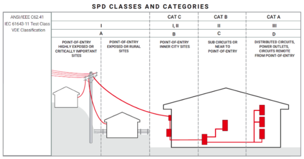
nVent ERICO recommends a coordinated approach with cascading SPDs throughout the facility. This allows the SPD located at the main service entrance to be selected to handle the maximum surge currents, while allowing a point of use SPD to be selected to minimize the let-through voltage. The two SPDs working together provide the best protection to the load.
In conclusion, SPDs are made up of various components, each with their own strengths and weaknesses. Industry standards provide the levels of performance a given SPD must meet, and the class or type defines the application for which an SPD is suited.
Learn More About Surge Protective Devices
Surge protection is a critical aspect of coordinated electrical protection for any facility. To learn how to keep sensitive equipment safe and limit downtime (among other benefits), download our Surge Protection Solutions Guide.