Understanding calculating ground electrode resistance of a single rod and its relation to ground electrode system design is key to understanding the fundamental principles of design, ground resistance and soil resistivity measurements and computations. This following is part one of our four-part ground electrode design principles and testing series, which is based on our white paper “Ground Electrode Design Principles and Testing.” You can download the full white paper here.
- Sheath Theory
- Soil Resistivity & Measurement
- Calculating On Ground Electrode Resistance Of A Single Rod
- Measurement Of Electrode Resistance
Calculating On Ground Electrode Resistance Of A Single Rod
The ground resistance can either be calculated using empirical formulae, by using nomograms or by the use of software.
Examples of formulae that are available for use are contained in AS1768 Lightning Protection Standard, Appendix C. The formulae enlisted below, extracted from AS1768, are two most commonly used.
1. Single vertical rod length L and diameter d meters, top of rod level with surface:
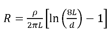
Where
R = resistance, ohms
ρ = soil resistivity, in ohm meters
L = buried length of grounding electrode, in meters
d = diameter of grounding electrode, in meters
Note: Equation is commonly referred to as the ‘modified Dwight formula.’
2. Straight horizontal wire of length L and diameter d meters, on surface:
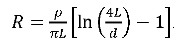
For a thin strip grounding electrode, the diameter can be replaced with a half-width of the strip.
Traditionally software programs have been able to carry out two layer models of ground resistivity. That means that resistivity measured had to be averaged out to two values with corresponding depths. Modern software can take multilayer resistivity values as an input.
In fact the real value of the software is not so much in computing resistance values for single or a few electrodes as this can be done easily with a formulae. However they can be powerful in calculating resistance of multiple ground electrodes, step and touch voltages and also simulating fault current injection.
Another method of calculating the resistance of a single ground rod, when the dimensions and the resistivity are known is using nomograms. In the example in Figure 1, a 7m ground rod, of diameter 10mm will produce a resistance of 7.6 ohms if the reading from the Wenner 4-Point test is 1 ohm.
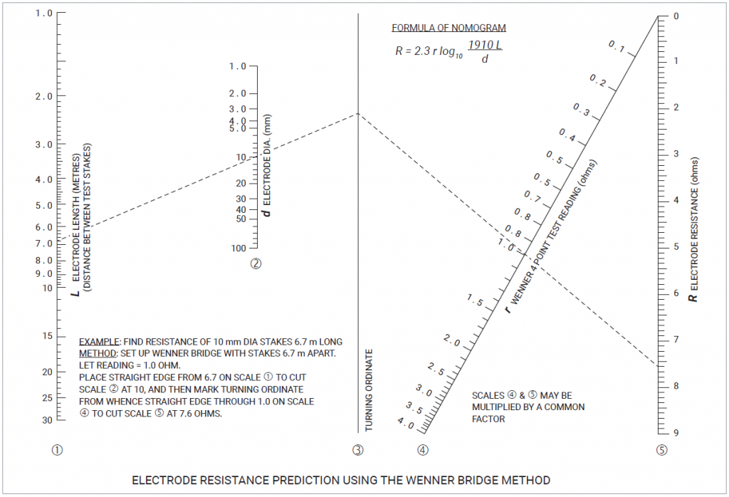
Figure 1: Nomogram to calculate resistance of a single ground rod
Calculating on Ground Electrode Resistance of Multiple Ground Rods
When ground rods are used in parallel it may seem at first that the resistance could be calculated by the simple equation 1/R = 1/R1+ 1/R2+ 1/R3…
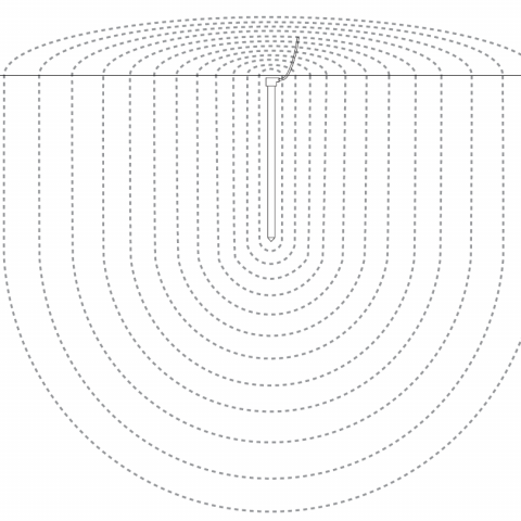
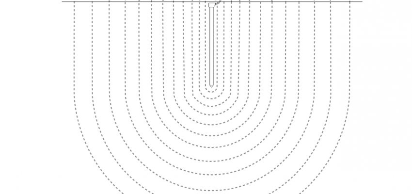
However, when one takes a closer look at the sheath theory discussed earlier, it becomes evident that the spacing between the ground rods may have some impact on the combined resistance. This is because the hemispherical sheaths of each of the electrode will overlap each other and the overlap area has to be compensated for. In the extreme case if two electrodes are superimposed to one another the size of the sheath offered by them will be similar to the sheath offered by one electrode. That is the resistance of two electrodes will be similar to that of one electrode if they are installed totally adjacent.
Rules of thumbs and utilization factors are used in everyday calculations to quickly compute parallel resistances without excessive analysis.
For example, when two electrodes are placed one electrode length apart, 85 percent utilization of their parallel resistance is achieved. When these electrodes are two electrodes apart, 92 percent utilization is achieved. We sometimes see a rule of thumb used in practice that states that the electrode spacing needs to be at least twice the electrode depth, based on this utilization.
Prior to the existence of software to carry out calculations, the use nomograms were the incumbent method of calculating resistance of multiple ground rods. There is no reason that these cannot be used today for quick calculations.
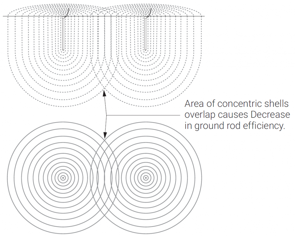
Figure 2: Parallel ground rods
Figure 3 shows a nomogram that can be used to design a multiple electrode system if the resistance of one electrode was known through calculation or measurement.
The calculation of the electrode resistance for a multiple ground rod system is a trivial matter when using modern-day software. It is essentially a matter of inputting the soil resistivity, electrode dimensions and the grid size layout and it will churn out a number, without too much fuss.
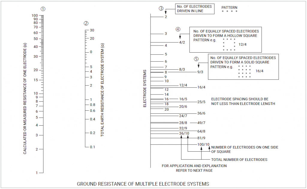
Figure 3: Ground resistance of multiple ground rods
Download the nVent ERICO Ground Electrode Design Principles and Testing White Paper
Download the white paper below that captures the fundamental principles of ground electrode design, ground resistance and soil resistivity measurements and computations. form a basis for understanding the reasoning behind incumbent grounding practices and will act as a guideline to an engineer trying to grasp the essence of ground electrode design.
Electrical Engineers: Your Source for Electrical News and Advice
Stay on top of new trends, advice and information by subscribing to the nVent ERICO blog. Our electrical engineering and product experts regularly publish new information, and also curate top resources with posts like this one.