 Grounding and bonding are an integral part of any modern electrical protection system design. An effective, low-impedance ground system is the foundation of an electrical system, regardless of structure type. It is crucial to help provide personnel safety, as well as reliable protection for vital equipment, as well as to minimize interruptions of service and costly downtime. Knowing the difference between grounding, bonding and earthing is imperative to properly design and install an electrical grounding system.
But first, let’s define the terms.
- Ground: A conducting connection, whether intentional or accidental, between an electrical circuit or equipment and the earth, or to some conducting body that serves in place of the earth.
- Earth: The conductive mass of the earth, whose electric potential at any point is conventionally taken as equal to zero. In some countries the term “ground” is used instead of “earth.”
- Bond: The permanent joining of metallic parts to form an electrically conductive path that will ensure electrical continuity and the capacity to conduct any current likely to be imposed.
The Need to Ground
There are important reasons why a grounding system should be installed, including:
- To protect people.
- Protect structures and equipment from unintentional contact with live conductors.
- Ensure maximum safety from electrical system faults and lightning.
It is a fundamental fact that electricity always flows to the point of lowest potential. The task is to ensure that electricity, including faults, lightning and electronic noise flows to this point with maximum safety to people, while maintaining the reliability of equipment. Therefore, we must ensure the safe, controlled flow of electricity with minimum voltage drop to earth in all cases.
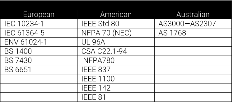
Grounding Codes and Standards
Grounding needs vary according to function. The grounding requirements of a power system will vary from those of electrical equipment, lightning protection or for the proper function of electronic equipment.
Proper installation of appropriate grounding systems requires knowledge of the needs and layout of the facility. Soil characteristics, grounding conductor materials and grounding connections and terminations, are significant factors determining the design of a grounding system. Applicable standards and codes must be applied.
While many codes and standards contain minimum grounding and bonding requirements, the design and installation of electrical grounding systems is one of the most important aspects of any electrical distribution system. However, codes and standards are often misunderstood and grounding systems subsequently installed improperly.
Why is Good Grounding Important?
The transient nature of lightning with its associated fast rise times and large magnitude currents mean that special consideration needs to be given to grounding for lightning protection to be effective. Many factors such as soil resistivity variations, installation accessibility, layout and existing physical features are all site-specific and tend to affect decisions on grounding methods employed. The primary aim of a direct strike grounding system is to:
- Efficiently dissipate lightning energy into the ground.
- Help protect equipment and personnel.
- Provide equipotential control.
Grounding Principles
Ground Impedance
Soil resistivity is an important design consideration. It varies markedly for different soil types, moisture content and temperatures, and gives rise to variations in ground impedances.
Short, Direct Ground Connections
The voltage generated by a lightning discharge depends primarily on the rise time of the current and the impedance (primarily inductance) of the path to ground. Extremely fast rise times result in significant voltage rises due to any series inductance resulting from long, indirect paths, or sharp bends in the routing of ground conductors. This is why short, direct ground connections are important.
Coupling from the Electrode System to the Ground
The efficiency of a ground electrode system in coupling a lightning current to ground is dependent on a number of factors, including the geometry of the ground electrode system, the shape of the conductors and the effective coupling into the soil.
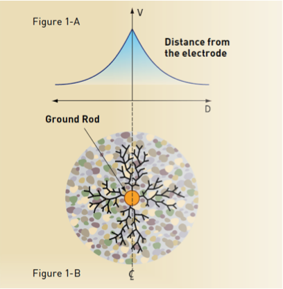 Figure 1-B illustrates current flow from the injection point of a single ground electrode. As current flows out from the central injection point, a voltage gradient on the ground surface around the electrode is produced. This gradient levels off to a plateau at some distance from the electrode, as seen in Figure 1-A. The impedance seen by the current is determined by the soil particles in direct contact with the surface of the rod, and by the general impedance of the soil.
The figure illustrates:
- Good electrical conductivity.
- Conductors capable of withstanding available electrical fault currents.
- Long life — at least 40 years.
- Low ground resistance and impedance.
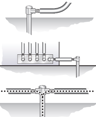
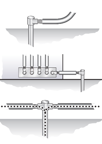
The basic philosophy of any grounding installation should be an attempt to maximize the surface area of electrodes or conductors with the surrounding soil. Not only does this help to lower the earth resistance of the grounding system, but it also greatly improves the impedance of the grounding system under lightning surge conditions.
Stay Up on the Latest in Grounding, Bonding and More
Want to stay updated on the latest tip and best practices in facility electrical protection? Subscribe to our blog to receive the latest information straight to your inbox.