 Lightning is a constant risk. A single direct strike can result in physical damage to buildings and cause catastrophic failure of sensitive electronic equipment. Lightning causes 22,600 fires per year and is the number one natural cause of system failures. As a result, these problems can result in substantial revenue losses.
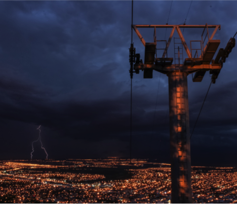
Telecommunications facilities are particularly at risk of direct lightning strikes—and the electrical surges that ensue—due to their tall stature and complex electrical makeup.
However, there is a way for engineers to protect telecommunication facilities from the devastating and lasting effects of lightning damage.
According to Above Ground Level Magazine, engineers can help protect telecom facilities from the dangers associated with lightning strikes using a six point plan of protection. Continue reading below to learn more about these six steps of lightning protection for telecom facilities.
1. Capture the Lightning Strike
Step one of the six point protection plan involves capturing the lightning strike via a rod or air terminal. Several different options exist depending on the structure size and height.
For example, the Above Ground Level article referenced above states that a conventional Franklin air terminal-type rod is adequate for telecommunication towers as tall as 140 feet.
2. Convey the Lightning Energy to Ground
Side-flashing or flashover occurs when lightning strikes a taller surface and a portion of the current jumps to a vulnerable structure or person. To mitigate this risk, lightning protection specialists rely on bonding and isolation.
Bonding is the primary method of conveying the energy of a lightning strike to ground, as it is easier than isolation to achieve. But, where communications systems use remote radio heads or where cable or feeder trays have been installed close to one tower leg, isolated systems do have advantages.
3. Dissipate the Energy Into a Low-Impedance Grounding System
For telecommunication sites, it’s recommended to use ground rings around buildings and towers. However, alternative arrangements can be used where space constraints do not allow for a ring that encircles the entire structure. Designers must pay close attention to keep the ring installations as symmetrical as possible to ensure the rings produce low earth potential rise during lightning flow.
Resistance to Remote Earth
The level of resistance to the earth is paramount to the dissipation of the energy through the ground. A widely accepted belief is that 5 ohms of resistance to a remote ground is the highest allowable value for telecommunications facilities.
When the soil resistivity is high or when the site has limited space for installing an earth grid, this low resistivity cannot be easily achieved.
Also, more complex sites may require lower ground resistances of 0.5 ohms to 2 ohms. Telecommunications operators should define their own ground resistance values in internal standards and guidelines.
Using predetermined design often achieves proper levels of ground resistance. Sometimes this approach produces varying results due to differences in soil resistivity among sites.
How to Choose the Right Grounding Materials
Several material types are available for each grounding component. Consider these when creating your system.
- For the conductors, copper wire is the most common grounding system material, as it exhibits excellent electrical conductivity, and, in most soil conditions, offers good resistance. The trade off is cost, as copper is relatively expensive, and often tempts thieves when used in exposed locations. Consequently, copper-bonded steel is becoming the conductor of choice. It offers a long service life like copper and is less expensive than steel. Thieves are also less prone to stealing steel.
>>Related Read: Combatting Copper Theft
- Ground electrodes: The three most common types of ground electrodes use copper-bonded steel. These provide the best long-term corrosion resistance relative to their cost.
- Grounding connections: In telecommunications, the most common grounding system connections use exothermic welds, bolted connectors and crimped connectors. ERICO CADWELD connections are the most common type of exothermic welding used with copper-based grounding systems.
- Ground bars: For decades, the material of choice for telecommunication ground bars has been tinned and bare copper. As copper theft becomes more common, alternatives are becoming more available. For example, some engineers turn to tinned aluminum and galvanized steel with a suitable amount of zinc coating.
4. Bond All Grounding Points Together
Compared to the six points for lightning protection, bonding all the grounding points together is the step with the lowest relative cost. Often, this results in engineers and installers overlooking this step.
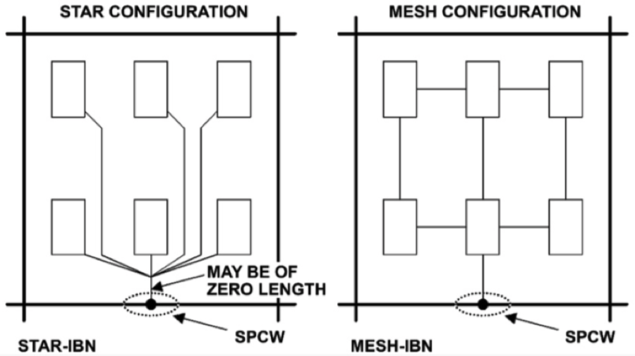
For telecommunications facilities, the Star-IBN and Mesh-IBN are the most common methods of bonding all the ground points.
- Star-IBN: The indoor grounding system connects via a single-point connection window (SPCW) to the ground electrode system. The SPCW usually takes the form of a ground bar, but can also be a ground ring inside the facility.
- Mesh-IBN: In this system, components inside the telecommunications facility are interconnected to form a mesh-like structure. The bonding mat is insulated from the common bonding network (CBN) of the adjacent room or building. Although there are multiple connection paths within the equipment room, there is only one point by which the Mesh-IBN connects to the external ground electrode system.
5. Protect Incoming AC and DC Power Feeders from Surges and Transients
Grounding controls many safety and noise considerations at a telecommunications facility. However, grounding alone does not fully prevent a transient or surge to the facility from outside. Surge protection devices are needed to mostly alleviate this concern.
AC Surge Protection:
- The problem: Lightning strikes near power lines or other power system disturbances can couple voltage transients or surges onto power lines. Lightning can couple onto power lines via a direct strike to the power line or via capacitive and magnetic coupling when lightning strikes nearby.
- The solution: Surge protection devices are normally open-circuit, but turn on when a higher voltage appears across its terminals during a transient voltage or a surge current. They momentarily create a short circuit to ground to allow the surge energy and divert it to the ground instead of going to the load.
- Keep in mind: Lightning surges and other power system transients are quite fast and can have extremely high amplitudes. Therefore, to be effective, surge protection devices must switch on quickly and handle large amounts of energy in a short time.
Also Consider DC Surge Protection
Traditional radio settings would keep damage limited to the radio equipment. Now, modern cellular and microwave equipment use a remote radio unit (RRU) or a remote radio head (RRH) fed from the base station via optical fiber. This method eliminates feeder loss and allows transmission to occur at much higher frequencies with wider bandwidth. As a result of modern installations, damage can occur to the rectifiers or the entire DC power system, which then would jeopardize other equipment installed at the site. This change increases the need for DC surge protection
6. Protect Low-Voltage Data and Telecommunications Circuits
Even if steps one to five are implemented, forgoing protection of low-voltage data and telecommunications circuits can be detrimental. Lightning can couple to telephone lines and RF feeders, leaving communication lines vulnerable to potential damage.
With telephone and data lines, surges can occur from each line to ground or across the lines. Protection against these surges requires the use of appropriately designed surge protection devices.
For coaxial feeders, surges are relatively small in comparison with total lightning energy. This is because the telecommunications tower and the cable ladders provide significant shielding to the feeder. The construction of the coaxial cable also provides excellent shielding to the inner conductor. Differential mode transients are not possible because there is one signal line and the other is the feeder screen, which is directly grounded at several locations.
As a minor precaution, coaxial feeders should be grounded at the top of the telecom tower where they bend close to the ground and enter the equipment room or cabinet. The feeder tray should be kept continuous in its trajectory along the tower. The feeder tray should be continuous when it leaves the tower and extend toward the equipment room or cabinet, preferably using a curved section at bends.
Where additional precaution is needed, coaxial surge protectors with appropriate connector type, bandwidth and surge ratings can be installed at the point of entry to the equipment building or cabinet.
Want To Learn More About Lightning Protection Best Practices?
Lightning may be unpredictable, but implementing a proactive solution can lessen the risks lightning pose to your telecommunications facility. Subscribe to our blog to stay up on the latest lightning protection tips and best practices.
Image credit: Unsplash