
Part 3 of 3 The considerations and relevant standards for the qualification of live conductor connections
Proper electrical and grounding connections are a small but essential element contributing to the overall reliability of an electrical installation. Connections, if improperly specified and poorly installed, can be the weakest component in the electrical installation and failures can lead to hazardous situations that will result in loss of life, significant property damage, or sever harm to the environment.
This article is the final in the electrical and grounding connection series discussing the LV live wire electrical connector applications and their related conditions to consider when selecting an appropriate means of electrical connection.
In Part 1 of this article, we discussed the common testing benchmarks and standards that are available, to validate grounding connections and verify the suitability of connectors for the application and the environment.
In Part 2 of this article, we discussed the asperity or A-spot model of a contact interface. These contact points or A-Spots are very small, in the order of micrometers in diameter and are distributed across an apparent contact area of a connection.
Intentional Path of Electrical Conduction
The primary function of electrical connections is to provide an intentional path of electrical conduction linking the conductors being joined. Secondly, the connection must maintain low contact resistance throughout its service life without deterioration, under all operating conditions, environmental or installation specific.
In electrical connections, the type of connector chosen is based firstly on the understanding of the primary application of the electrical circuit which defines purpose of the connection and the physical environment. Special connectors are engineered and tested for the desired application.
Secondly the desired function of the connection specifies the selection of the connector. These functions are tap connector which attaches the secondary branch electrical circuit to the main primary circuit, terminal connectors which is used to connect conductors to a device or busbars, and splice connectors to join two or more conductors together.
Finally the connectors generally fall into three board categories of Mechanical, compression and Fusion (Exothermic) connection which was discussed in details for grounding application in the previous parts of the electrical and grounding series.
In this article , Mechanical and compression connections which is most common method of LV electrical connection will be discussed. Mechanical connections employ hardware or similar mechanical means to create contact points and to maintain the connection integrity. These connection is designed to accommodate the current carrying capacity of the conductor and provide ease of installation, resulting in a safe, reliable electrical connection especially when installed at the as per manufacturers instructions.
Compression connections use specialized tooling to crimp the connector to the conductor with high force, creating a permanent electrical joint.
Standards and Testing
There are various standards that provide application recommendations and performance criteria to which electrical connections are tested associated with the environment and conditions to which a connector will be exposed over its lifetime. The compliance of the test provides the user with reasonable assurance that the connection tested is suitable for the application.
The mechanical and compression connection are expected that when in service in both normal operation or under short circuit condition, the resistance of connector will remain stable, the temperature of the connector should be same or less then the conductor and mechanical strength should be fit for the purpose.
AS/NZS 4325 technically equivalent to IEC 1238-1 provides test method and requirements for compression and mechanical connectors for power cables with copper and aluminium conductors. The test under AS/NZS 4325 is not applicable to overhead conductors such as insulation Piercing Connectors which are designed for special mechanical requirements are covered under separate standard.
Class A connectors which are intended for electricity distribution or industrial network in which the conection is subject to high short circuit currents and duration are subject to both heat cycle and short circuit test.
Class B connectors are for networks in which overloads or short circuits are rapidly restricted by the installed protective devices are only subject to heat cycle tests.
Additional tests may be required for situations where the connector may experience high temperature by virtue of connection to highly rated plant, subjected to excessive mechanical vibration and sock or corrosive conditions.
International standards such as UL486A and UL486B Standard applies to testing of single-polarity connectors for use with all alloys of copper or aluminum, or copper-clad aluminum conductors, or all three, for providing contacts between current-carrying parts, in accordance with the Canadian Electrical Code, Part I, C22.1, in Canada, the National iElectrical Code, NFPA-70, in the United States of America, or the Standard for Electrical Installations, NOM-001-SEDE, in Mexico.
Furthermore, ANSI C119.4 specifies current cycle and mechanical tests for establishing a basis of performance for electrical connectors used to join aluminum-to-aluminum or aluminum-to-copper bare overhead conductors. As a connector tested on bare cable is a more stringent test, this standard is also used to test electrical connectors that will be jacketed and covered.
These standard provides well-defined, reproducible requirements for electrical connectors and assures the user that connectors meeting these requirements will perform in a satisfactory manner when properly installed.
Compression Connection
Compression connectors are part of a connection system that utilizes specific installation tools and dies for installing permanent, high quality connections. The versatility of a compression system ensures that all connector functions (tap, terminal, and splice) are attainable in numerous forms. In addition, compression connectors are available for both aluminum and copper conductors.
Compression connectors are also most suitable in areas of wind, vibration and other stresses associated with tension applications.
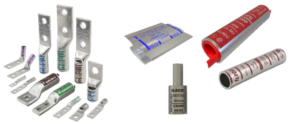
Figure 1 Examples of electrical compression connectors
Compression Tooling
Compression connectors are installed with engineered tooling. The use of matched tool, die and connector combinations from a same manufacture is important when installing the compression connector. The matching combination is guaranteed tested with the compliance standards as a complete connection. A compression tool, whether mechanical, hydraulic, or battery powered can accommodate a range of connectors. Selecting the proper tool for your application is the first step to making a sound electrical connection. Crimp dies are designed with a particular tool, connector and conductor application. Therefore, the die selection is an important component in the compression installation process. The connector will normally be stamped with the die index codes to indicate suitable crimp dies. Finally, die selection will need to also match the installation tool chosen. Installing the compression connector requires the correct number of crimps to be applied with the tool and die. Making too few crimps can seriously impair the long-term performance of a connection. Clearly marked color bands indicate both the position and the number of crimps to be applied.
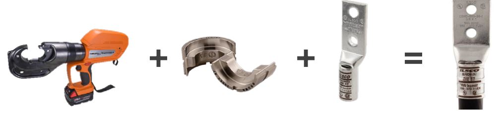
Figure 2 matched tool, die and connector from same manufacture provides a reliable compression connection
Mechanical Connections
A variety of mechanical connectors are available to satisfy all tapping, terminating, and splicing in electrcal application applications. These are available in copper and aluminum and usually can accommodate a range of conductor sizes. Special considerations are given to the connector design to obtain and maintain a proper contact pressure without damaging the conductor and connector itself under the installation conditions and applications. Overhead mechanical connectors have special mechanical requirements.
Mechanical connectors are generally prefered where non-perminant connection is required.
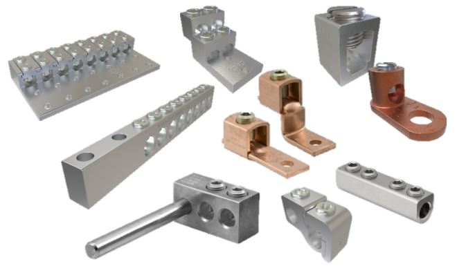
Figure 3 Examples of Mechanical Connectors
Insulation Piercing Connectors
Insulation piercing connectors are particular subset of mechanical connectors where the connection is made by the connectors teeth piercers through the cable insulation and make good electrical contact with the conductor. The connector is prefilled with oxide exhibiting compound and comes with shear head bolt to negate the use of torque wrench. The connection is waterproof once the connection is made and does not required any additional waterproofing compound or covering. The main advantage of IPC is that no insulation striping is required to make the connection.
IPCs are generally used for electrical tap connections between the insulated LV overhead or underground mains and insulated branch cables. Various combination of IPC and other mechanical connectors are used for these applications. For example combination of mechanical clamp type connector and IPC for connecting bare overhead mains conductors to insulated service mains conductors or a combination of IPC with tunnel type terminal for house service connections. The IPC connectors are required to be tested to AS/NZS 4396 which specifies the functional and test requirements of insulation Piercing connectors to make connections between the 0.6/1 kV ariel bundle cables and insulated branch cables.
Underground Connectors
Underground electrical connections are very complex. The underground environment is often unpredictable in temperature variation, continuous presence of moisture, connections may be submerged due to flooding, and exposed to corrosive environment. Access to connections are usually limited. It is for this reason connections for underground applications are specially designed for ease of installation, compactness, and able to be completely insulate for any water ingress.
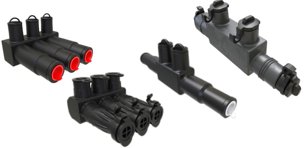
Overhead Connectors
Selection of connectors for use on overhead applications is dependent on conductor material aluminum (AAC, AAAC, ACSR) or copper, whether it is bare conductor or insulated, connection is made on a tension or non-tension line conductor, operating voltages and environmental conditions. All materials used in the construction of the connector is required to be inherently resistance to atmospheric corrosion, which may affect its performance.
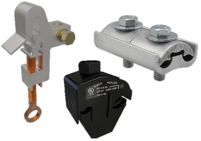
Figure 4 Example overhead tap connectors
Special Safety Connectors
Streetlight poles require special consideration for the connection, where the connectors are designed so that during an accident where the street light pole is rundown by motor vehicle, the live electrical connector safely provides a breakaway connection with a touch safe separation joint, without endangering the vehicle occupant, paramedics or the general public on the street.
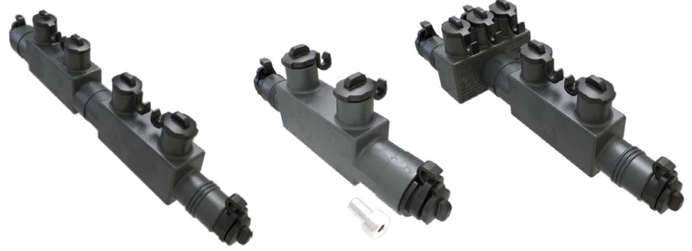
Figure 5 Streetlight breakaway modular connectors
Torque Compensating Terminals
Various methods have been used to make a reliable mechanical terminal connection. Torque compensating screw is utilized in mechanical connectors to accept fine stranded conductors and eliminates damaging conductor strands which would otherwise reduce the integrity of the connection.
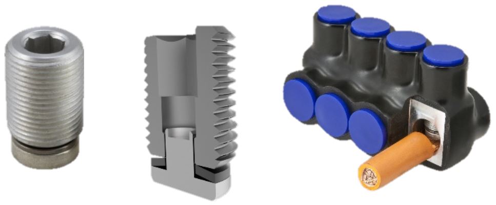
Figure 6 Torque compensating screws used in mechanical terminal connections
Corrosion
There are two general types of corrosion that are of concern when selecting electrical connections method. Oxidation and galvanic corrosion affect both the initial contact and the long-term performance of an electrical connection.
Galvanic corrosion takes place mainly through galvanic action when two dissimilar metals come in contact when exposed to an electrolyte. This type of corrosion is most pronounced when the connector material differs significantly from the conductor material in nobility. Over time, the loss of material at the connection interface whether it is from the connector or conductor will cause an increase in electrical resistance resulting in a reduction in overall performance and possibly loss of contact. Like-metals in direct contact are less subject to galvanic corrosion because they are close in electrical potential.
In the instance of water run-off from copper- the water carries fine copper corrosion particles which, when they drop on to aluminium or zinc, may result in corrosion. The direct contact of the dissimilar metals are not required for corrosion to occur in such a case.
Bimetallic connectors are used to connect copper and aluminum conductors to avoid galvanic corrosion.
Both copper and aluminium oxidize on contact with air. The contact surface of copper oxide is soft and electrically conductive and can be easily broken to make good contact, whereas aluminium oxide which forms immediately on exposure is strongly attached, hard and develops a high electrical contact resistance.
Surface preparation is essential to ensure proper contact is made between connector and conductor. Oxidation and contaminants on the surface that get between the mating contact will greatly interfere with the establishment of a good electrical connection.
Mechanical and compression connections generally require coating contact surfaces with an oxide inhibiting compound. These compounds have many attributes that ensure good contact and enhance the longevity of the connection.
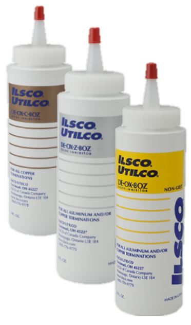
Figure 7 Oxide inhibiting compound
Summary
The primary objective of the electrical and grounding connections is to provide a low resistance joint which remains stable under normal and fault conditions, must be durable and robust , fit for the intended purpose and withstand the mechanical forces and corrosion over its lifetime.
When selecting a connection method for any electrical or grounding applications, the user must have a good knowledge of connection function or its application. Secondly the awareness of the environmental and conditions to which a connector will be exposed to over its lifetime. Thirdly, the user must have a knowledge of connector degradation mechanism that will exist in the environment that the conductor is subject to during its intended service (design) life.
The user must also be aware of the standards associated with the testing of the connection for its intended application which provide both applications and performance criteria to which the connection is tested. The performance tests are directly associated with the environment and conditions to which the connection will be exposed over its lifetime. For example IEEE std 837 testing criteria simulates the substation grounding connections.
If you want to learn more about nVent ERICO, please visit our website, www.nvent.com/erico.
CONTACT US