
Proper electrical and grounding connections are a small but essential element contributing to the overall reliability of an electrical installation. Connections, if improperly specified and poorly installed, can be the weakest component in the electrical installation and failures can lead to hazardous situations that will result in loss of life, significant property damage, or severe harm to the environment. Damage to equipment?
In Part 1 of this article, we discussed the common testing benchmarks and standards that are available, to validate grounding connections and verify the suitability of connectors for the application and the environment.
Part 2 of this article discusses the asperity or A-spot model of a contact interface. These contact points or A-Spots are very small, in the order of micrometers in diameter and are distributed across an apparent contact area of a connection.
In connectors, the roughness on the contact surfaces causes added electrical resistance (known as electrical contact resistance (ECR)).
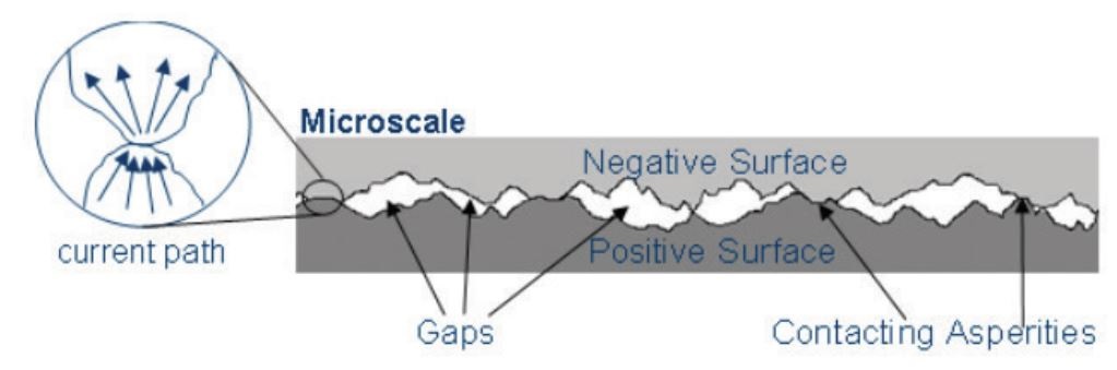
Schematic of “bottlenecked” current flow
There are many different methods to model the contact of surfaces including statistical , fractal, and multiscale models. The fractal mathematics based methods were derived to account for different scales of surface features not accounted for by the statistical models. The multiscale models were developed to alleviate the assumption of self-affinity imposed by fractal mathematics and also improve how the mechanics are considered [1].
For the purpose of this discussion it is suffice to state that many models exist that can be used to understand connections better with scientific modelling.
These asperity spots and electrical contact resistance will exist even if similar metals are used for connections such as copper to copper. The level of asperity spots are expected to vary for different connection types like mechanical connections, compression connections and exothermic connections. At nVent, we provide a comprehensive range of connectors for all requirements.
If any of the asperity interfaces are compromised by corrosion films or contaminants, the electrical contact resistance will increase. This is the reason why corrosion is a degradation mechanism for connectors. Loss of asperity contact area, or of asperity contacts, due to corrosion or contamination can result in contact interface resistance increases leading to connection failures over a period of time.
The contact resistance can also increase over time in a grounding connection due to application of repeated fault currents.
There are broadly three (3) type of electrical connections, namely mechanical, compression and exothermic, that are used in grounding and live wire applications. Mechanical connectors are designed to be reused whereas the compression and exothermic connectors provide irreversible permanent connections.
Mechanical Connections
The objective of the mechanical connector is to establish a proper connection having low contact resistance, but which can be easily disconnected and reconnected with consistent performance over the service life in live wire applications. Special considerations are given to the connector design to obtain and maintain a proper contact pressure without damaging the conductor and connector itself under the installation conditions and applications. Overhead mechanical connectors have special mechanical requirements.
Mechanical or bolted connections exhibit the least amount of asperity spots and overtime are the most vulnerable to degradation, via heating and corrosion, especially those in exposed locations. Generally mechanical connectors are not recommended for buried grounding connections. If these are used underground consideration has to be given to dissimilar metals, waterproofing using self amalgamating tape and inspection wells or pits. In these connections, there is higher concentration of current flow at the A-Spots and hence this leads to build up and concentration of heat. While conductor and connection may be physically be built to carry the currents, the relatively low level of A-Spots may still cause heating and high resistance problems in live wire applications.
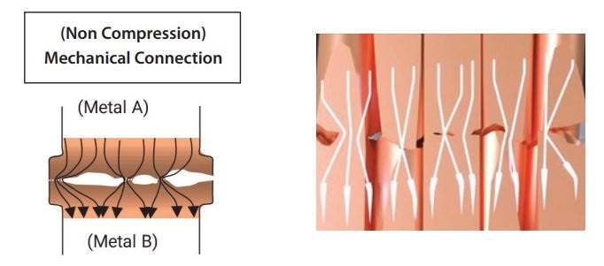
Depiction of Current Distribution Across Mechanical Connections
In part 1 of this article several standards for testing and qualification of connections for grounding and lightning protection applications were identified. Mechanical connectors when properly designed can pass some of these standards like UL 467 – UL Standard For Safety Grounding and Bonding Equipment and IEC 62561-1:2023 Lightning Protection System Components (LPSC) – PART 1: Requirements for connection Components.
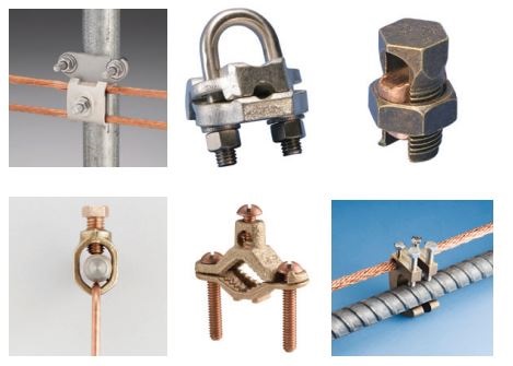
Examples of Mechanical Bolted Connections
Connector design and manufacturing companies who develop these mechanical connections often find that to pass these standards, mechanical connections usually need to undergo several modifications and design changes during the development of these connection products.
Furthermore there is a need to specify an installation torque, cable and conductor range as well as configuration requirements which are used in the testing and development phases. The certainty that these torque and configuration requirements are met in the field application of these connections is impossible to ascertain.
Compression Connections
Compression connections are irreversible permanent connections where a connector is intentionally deformed (compressed) under pressure with the specific designed tools and techniques. The objective is to establish large-area metal-to-metal contact, and maintain the connection under any desired environmental condition for the intended service life. When used in buried ground applications, these are generally all copper connections hence there is less of a concern about galvanic corrosion. However these connections are still subject to other types of corrosion below ground.
Compression connections exhibit significantly better asperity spots in comparison to mechanical connections, hence there is much lower degradation, heating and corrosion over time in these connections .
Certain live wire applications require full tension cable splices as for instance, on overhead lines. For these cases, multiple crimping is more satisfactory. Each crimp contributes to the total tensile strength, and improved Asperity. Similarly long barrel compression lugs are designed for multiple crimping.
The compression connection is a complete system – involving combination of component, tooling, and techniques to make an effective connection. To make a proper connection, firstly the connector has to be suitably designed, type tested and selected for the correct application. Secondly correct tools have to used and the required compression force needs to be applied. Thirdly, the compression die has to be correctly selected for the required conductor size. Lastly the compression tool has to be used correctly appropriately.
Typical hydraulic tools used to create compression connection have a significant force of 6-12 Tons that is used to crimp-in the compression connection around the conductors.
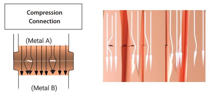
Depiction of Current Distribution Across Compression Connections
For grounding applications, compression connectors, when properly designed can pass standards like UL 467 – UL Standard For Safety Grounding and Bonding Equipment and IEC 62561-1:2023 Lightning Protection System Components (LPSC) – PART 1: Requirements for connection Components with relative ease.
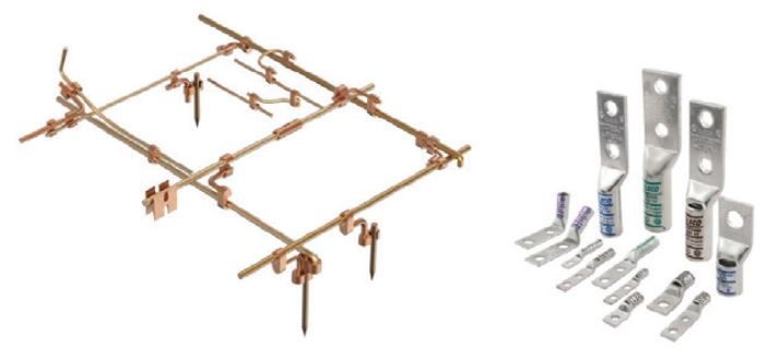
Examples of Compression Connections
However, these connections have difficulty in passing the more stringent IEEE STD 837-2014: Standard for Qualifying Permanent Connections used in Substations. Most compression connections may pass ONLY PARTS of this more rigorous standard for substation application.
The standards for live wire or active electrical connection will be discussed in part 3 of this article and for now it is suffice to say the compression connections will pass most of these electrical standards.
The performance of these connections depend on the correct tool, compression force and the crimping dies and during the testing these can be selected easily.
However tools and dies that exist in the market place and in tool boxes of trades personnel can vary significantly to the connector manufacturers. The best outcome is guaranteed when these tools and crimp dies are selected from the manufacturer. Good connector manufacturer takes the extra initiative to test their connections with other tools and crimp dies commonly used in the industry. nVent provide significant amount of cross reference information of its connections with other tools and dies.
Exothermic or nVent ERICO Cadweld Connections
nVent ERICO Cadweld or Exothermic welded connections have the highest amount of asperity spots and hence is the ultimate electrical connection that is the least susceptible to degradation, heating and corrosion over time in exposed locations. In these connections the A-Spots are across the whole connection and hence there is no build up and concentration of heat. In theory the connection can be the same size as the connector.
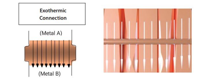
Depiction of Current Distribution Across Exothermic or nVent ERICO Cadweld Connections
For grounding applications, exothermic connection pass UL 467 – UL Standard For Safety Grounding and Bonding Equipment and IEC 62561-1:2023 Lightning Protection System Components (LPSC) – PART 1: Requirements for connection Components with ease.
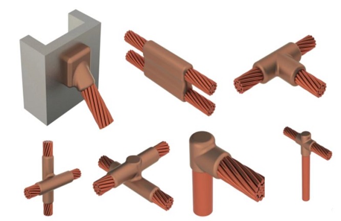
Examples of Exothermic or nVent ERICO Cadweld Connections
Connections and conductors that are commonly used in electrical substation also fully comply with and pass in its entirety with IEEE STD 837-2014: Standard for Qualifying Permanent Connections used in Substations.
The use of exothermic connections historically has largely been the grounding and bonding applications. There are some limitations of its use in indoor applications due to the intense heat from the exothermic reaction. Applications for exothermic connections do exist at indoor locations with additional precautions taken to contain the smoke from the reaction. For this reason exothermic or nVent ERICO Cadweld is the most popular connection method for high performance grounding applications.
The creation of exothermic connections depends on the selection of correct molds, weld metal and accessories like electronic ignition unit.
There is no compatibility issues to be dealt with unlike compression tools and crimp dies because the exothermic system of connection will almost always be supplied by one vendor.
Other Connection Types
There are other categories of connection that are in-between bolted mechanical and compression which have much better control during installation than bolted mechanical connections. These may be hammer on type or shear bolts type. The hammer-lock type connections sleeves onto conductors like ground rods with a piston type mechanism for the cable conductor. The shear lock type connections has shear bolts that will eventually break at the correct shear strength, when being tightened. This provides a more definitive torque control.
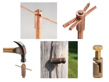
Hammer Lock and Shear Type Connections
The shear type connections are used in grounding and live wire applications. The hammer lock type connections are primarily used in grounding applications.
These other connection types will exhibit better performance than bolted mechanical connections under some of the above mentioned standards.
Conclusion
As mentioned in the part 1 of this article, when selecting a connection method for any electrical or grounding application, there are two key considerations the user must be aware of in choosing the best connector in order to ensure consistent, durable and reliable connectivity.
1.The first is the knowledge of the environmental or installation locations and electrical operating conditions that the connector will be subjected to in its service life.
2.The second is the knowledge of connector degradation mechanisms that will exist in the environment that the conductor is subject to during its intended service (design) life. Surface contaminants or corrosion will interfere with establishing good initial contact, thermal fatigue can loosen the connector and reduce the number of contact points. Further, mechanical stress and long term corrosion can diminish surface contact directly or indirectly by attacking the structural integrity of the connector.
The additional information in this article will further help in the selection of connection through a better understanding of how different connections behave under the Asperity Spot or A-Spot model of connector theory.
Read Part 1 of 3 here: https://blog.nvent.com/electrical-grounding-connection-technologies-part-1-of-3/
Reference
[1] Electrical Contact Resistance Considering Multi-Scale Roughness W. Everett Wilson, Santosh V. Angadi, Robert L. Jackson, Department of Mechanical Engineering Auburn University, Auburn, AL 36849-5341
[2] Connector Degradation Mechanisms—Corrosion Part I By Dr. Bob Mroczkowski June 19, 2007
[3] Grace Under Pressure: Shelley Green Celebrated Crimped Connections April 27, 2020 by Kristina Panos, Hackaday
[4] Simplified Calculation Model for Contact Resistance Based on Fractal Rough Surfaces Method by Changgeng Zhang, ORCID,Baichuan Yu, Yongjian Li. andQingxin Yang
[5] Fractal Roughness and Electrical Contact Resistance J.R.Barber University of Michigan https://public.websites.umich.edu/~jbarber/rough.html
[6] A rough surface electrical contact model considering the interaction between asperities You-Hua Li a, Fei Shen a b, Mehmet Ali Güler c, Liao-Liang Ke
If you want to learn more about nVent ERICO, please visit our website, www.nvent.com/erico.
CONTACT US