
Proper electrical and grounding connections are a small but essential element contributing to the overall reliability of an electrical installation. Connections, if improperly specified and poorly installed, can be the weakest component in the electrical installation and failures can lead to hazardous situations that will result in loss of life, significant property damage, or sever harm to the environment.
The primary function of electrical and grounding connections is to provide an intentional path of electrical conduction linking the conductors being joined. Secondly, the connection must maintain low contact resistance throughout its service life without deterioration, under all operating conditions, environmental or installation specific.
Two Key Considerations
When selecting a connection method for any electrical or grounding application, there are two key consideration the user must be aware of in choosing the best connector in order to ensure consistent, durable and reliable connectivity.
1. The first is the knowledge of the environmental or installation locations and electrical operating conditions that the connector will be subjected to in its service life.
Example 1: A buried grounding connector in an electrical substation during fault conditions will be subject to rapid heating due to high current magnitude, high mechanical stress due to electromagnetic forces, exposed to environment with corrosive soil (alkaline and acidic) and the continuous presence of moisture.
Example 2: An above ground, live electrical connector inside a protected switchboard enclosure. With the circuit being live, the connector will be subject to continuous current cycles in normal conditions with no exposure to the environmental elements other than the ambient air temperature. Under fault condition the conductor will be subject to mechanical stress and temperature rise.
Example 3: Connectors in an underground distribution system are often exposed to unpredictable temperature variation, continuous high moisture content and even flooding. Physical access may be very limited in many cases.
2. The second is the knowledge of connector degradation mechanisms that will exist in the environment that the conductor is subject to during its intended (design) life. Surface contaminants or corrosion will interfere with establishing good initial contact, thermal fatigue can loosen the connector and reduce the number of contact points. Further, mechanical stress and long term corrosion can diminish surface contact directly or indirectly by attacking the structural integrity of the connector.
This article is divided into three sections:
• The first discusses common testing benchmarks and standards that are available, to validate grounding connections and verify the suitability of connectors for the application and the environment.
Sections two and three will appear in future publications and will discuss:
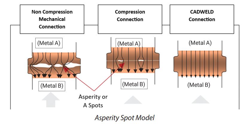
• Part 2 The asperity or A-spot model of a contact interface. These contact points or A-Spots are very small, in the order of microns in diameter and are distributed across an apparent contact area of a connection.
 • Part 3 The considerations and relevant standards for the qualification of live conductor connections
The most common joints between grounding conductors include exothermic welds (such as nVent ERICO Cadweld), compression & mechanical clamps.
IEEE Std 837 – Standard for Qualifying Permanent Connections Used in Substation Grounding
IEEE Std 837-2014 provides direction and methods for qualifying permanent connections used for substation grounding. It particularly addresses the connection used within the grid system, the connection used to join ground leads to the grid system, and the connection used to join the ground leads to equipment and structures.
The purpose of this standard is to give assurance to the user that a connection meeting the requirements of this standard will perform in a satisfactory manner over the lifetime of the installation, provided that the proper connection is selected for the application and that the connection is installed correctly.
Grounding connections that meet the test criteria stated in this standard for a particular conductor size
range and material should satisfy all of the criteria for connections as outlined in IEEE Std 80™ Guide for Safety in AC Substation Grounding and other standards including any Australian Standards that requires the connector to be in compliance with IEEE Std 837. IEEE Std 837-2014 is the highest benchmark for the ultimate grounding connection and it takes full account of the worst case connector degradation over the intended design life of the connection. It exceeds the requirements of all other ground standards. Mechanical strength and electrical resistance are tested with pullout and electromagnetic mechanical strain tests, longevity is proved through a sequence of tests on the same set of connector-cable specimen that go through static heat cycling, freeze-thaw cycling, corrosion exposure (acidic and alkaline) and fault current test.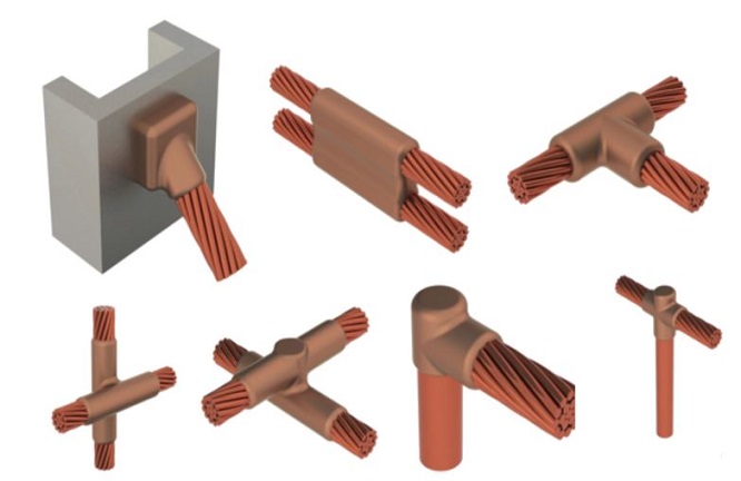 An example of a connection method that fully complies with this standard are nVent ERICO Cadweld connections when used with appropriate sized conductors and ground rods.
UL 467 – UL Standard for Safety Grounding and Bonding Equipment
This Standard applies to grounding and bonding equipment for use in accordance with CSA C22.1, Canadian Electrical Code, Part I in Canada, the National Electrical Code, NFPA 70, in the United States, or the Standard for Electrical Installations, NOM-001-SEDE, in Mexico. Additionally UL 467 may be called for in specifications and construction standards within in Australia and other parts of the world. This Standard applies to but is not limited to all grounding and bonding equipment.
By meeting the requirements in this standard, the user can be confident that the connector is likely greater than 80% copper (if marked “direct burial”) and has withstood a short time current test. If the connector is made of a material containing less than 80% Cu, it is subject to additional corrosion testing in order to determine if it can be used in the ground. Alternate connector testing may be substituted, but none should require less than the criteria in the above standard. The criteria for passing the UL 467 are not as stringent as IEEE837-2014.
ENA (Australia) EG-0 Power System Earthing Guide Part 1: Management Principles
This Guideline addresses the high-level aspects of management policies and strategies associated with power system earthing. It is intended for use by electrical utilities and HV asset owners, operators and customers. EG-0 stipulates that grounding connectors particularly compression fittings or exothermic products used for jointing conductors shall comply with the requirements of an acceptable standard such as IEEE Std 837.
Under this guideline bolted joints are not considered acceptable for direct burial. Corrosion issues associated with joints should be considered, especially where dissimilar metals are involved. Corrosion of the conductors and connectors may result in the joint becoming loose or developing a high impedance. The use of joint sealing compounds may also be considered where appropriate to ensure water and other contaminants do not penetrate the joint.
ENA(Australia) EG-1 Substation Earthing Guide
EG-1 provide guidelines for the design, installation, testing and maintenance of earthing systems associated with electrical substations. Earthing systems that are covered in this guide include those associated with generating plant, industrial installations, transmission and distribution stations. EG-1 states that grounding connector selection should be made on consideration of the following two criteria based on international standards that specify functional performance type test requirements for earthing connectors such as IEEE Std 837.
Firstly, to demonstrated performance in type test conditions relevant to the operating conditions, environment or installation location and secondly the connectors must be capable of handling the thermal and mechanical requirements of the design.
IEC 62561-1:2023 Lightning protection system components (LPSC) – Part 1: Requirements for connection components
The IEC 62561 series of standards covers lightning protection system components, including connectors (part 1), conductors and earth electrodes (part 2), isolating spark gaps (part 3), conductor fasteners (part 4), earth electrode inspection pits and housings (part 5), lightning strike counters (part 6) and earthing enhancement materials (part 7).
IEC 62561-1:2023 specifies the requirements and tests for metallic connection components that form part of a lightning protection system (LPS). These components include connectors, clamps, bonding and bridging elements, expansion pieces, and test joints. The standard ensures their reliability and compatibility within the overall lightning protection system.
Significant changes in this latest standard include a change in the scope that now includes definitions of various connection types. It has an expanded location classification, to which detailed information has been added. There is alignment with ISO 22479:2019, which addresses components in a humid sulfurous atmosphere and a new annex provides revised test procedures.
Other Standards
Other standard worth referencing are the British Standard BS7430 Code of practice for protective earthing of electrical installations and ENA(UK) TS 41-24 Guidelines for the Design, Installation, Testing and Maintenance of Main Earthing Systems in Substations.
Summary
The assessment of the environment that the connector will be exposed to during its service life and the knowledge of connector degradation mechanisms that will exist in this environment are critical parts to the selection of electrical connections. Standards referenced here can provide useful guidance in the testing and selection of electrical connections used for grounding applications.
If you want to learn more about nVent ERICO, please visit our website, www.nvent.com/erico.
CONTACT US